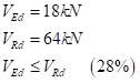
In this article, we will design an Angle section in pure compression, considering its principal axes (u-u & v-v).
Keywords: Advance Design, Angle, Eurocode 3, EN 1993-1-1
1.Introduction
ke most steel structural members, angle sections are designed not in their geometrical axes (y-y & z-z, parallel to the legs) but in their principal axes (u-u & v-v).
2. Theory
The Eurocode 3 convention for member axes refers to the axes about which the moment acts.
For most sections, that would be the geometrical axes (y-y & z-z):
y-y is the cross-section axis parallel to the flanges
z-z is the cross-section axis perpendicular to the flanges
Yet, this convention is not suitable to angle sections, for which bending occurs about the principal axes (u-u & v-v).
Therefore, the u-u & v-v axes should be used instead:
u-u major principal axis
v-v major principal axis
3. Application
Assume a L 90×9 equal leg angle, subjected to a NEd = 80 kN compressive axial force.
Steel grade is S275.
The effective slenderness (λeff) refers to annex G from EN1993-3-1:
EN1993-3-1 (Annex G)
The effective slenderness involves a k parameter, which depends on the type of restraint, as per Table G.2 from EN 1993-3-1.
For buckling about the v-v axis though, the k formula is unchanged.
Table G.2 from EN1993-3-1
The angle section under consideration is properly designed.
4. Conclusion
Angle sections should be designed about their principal axes, especially in pure compression situations, where buckling typically arises about the v-v axis.
The upcoming update of Advance Design (version 2023.1) will enable this option, while letting the user consider the effective slenderness ratio.
The present article goes one step further by considering the interaction between several walls, and the sheltering effect they may produce on each other.
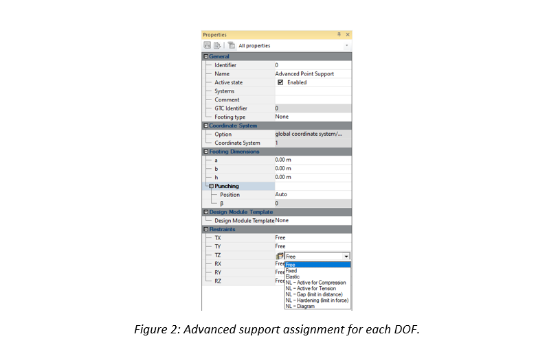
In addition to these supports, a user defined nonlinear support mechanism is also possible (“NL-Diagram” option in Figure 2).
2. Theory
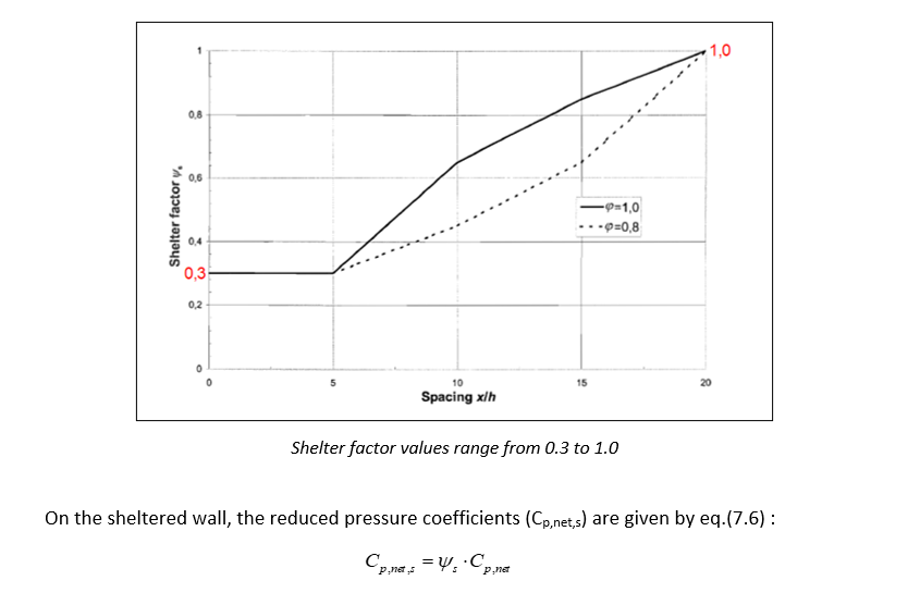
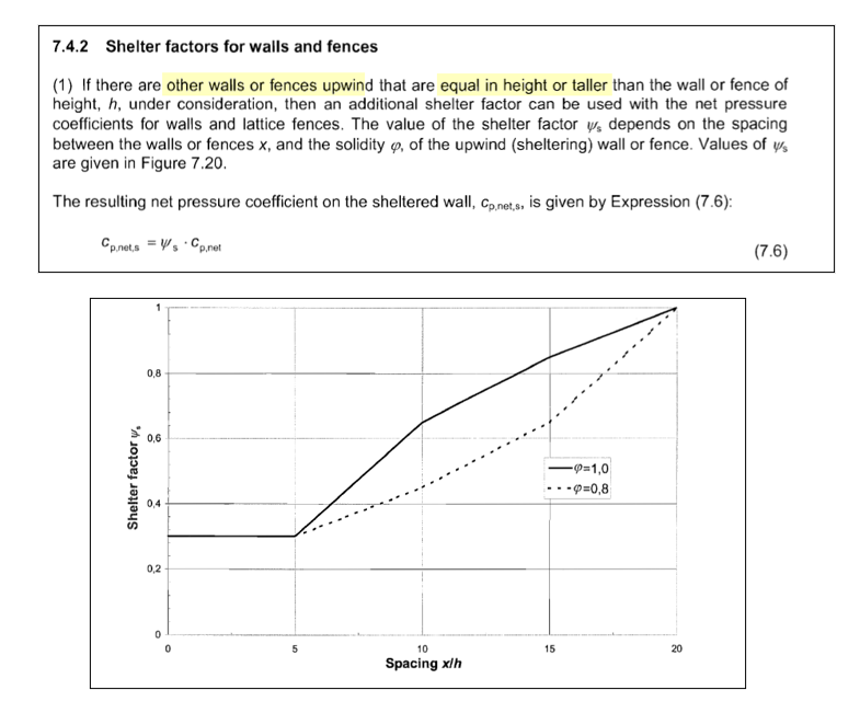
Shelter factor is defined in §7.4.2 from EN1991-1-4.
This coefficient will reduce the pressure coefficients when an upwind wall is able to provide protection to the wall under consideration.
The shelter factor can be determined on Figure 7.20, based on:
The spacing between the two walls (x)
The solidity ratio of the sheltering wall (φ)
The height of the sheltered wall (h)
3. Example
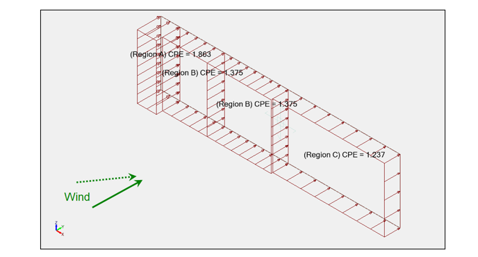
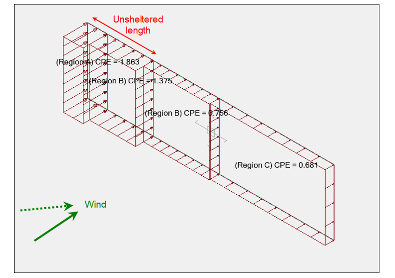
Assume a 15m x 4m wall, with a φ = 0,9 solidity ratio.
The pressure coefficients on this isolated wall would be:
Zone A: Cp,net = 1,863
Zone B: Cp,net = 1,375
Zone C: Cp,net = 1,237
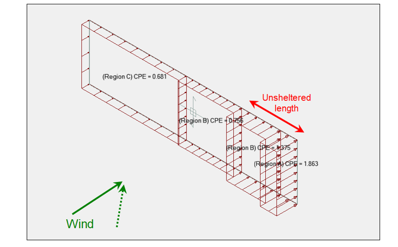
Now, if a similar wall, were to be located at a 40m distance, it would produce a sheltering effect that would be introduced in the calculation through the shelter factor.
Of course, the alternate oblique wind direction should be considered as well:
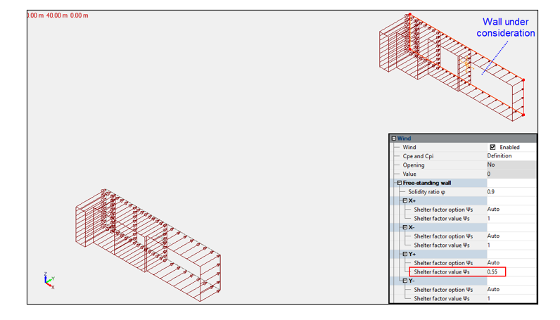
The climatic generator Advance Design is able to automatically detect the potential upwind walls and to compute the corresponding shelter factor for each wind direction.
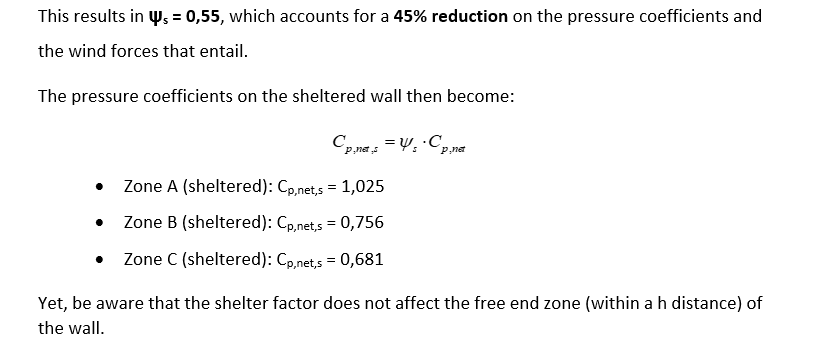
On the picture below, Advance Design detected that the wall under consideration could benefit from the sheltering effect of an upwind wall for the Y+ wind direction, resulting in ψs=0,55.
Yet, no such walls were detected in the other directions, resulting in ψs=1,0 for the X+, X- and Y- directions.
4. Conclusion
When designing a wall or a fence for climatic actions, the determination of the shelter factor can be a lengthy and tedious process, yet totally worthy as it can allow for a significant reduction of the wind forces.
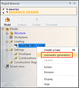
Fortunately, in Advance Design, the detection of the potential upwind walls with the shelter factor they produce, is performed instantly during the automatic wind generation.
This article presents application examples of nonlinear advanced supports. The purpose is to highlight how these supports work and the different mechanisms they have.
Some structures require special type of supports such as:
Supports that work only in tension or compression (tension or compression only supports).
Supports that allow displacements/rotations within specified limits. Once these limits are reached, the supports are activated and no further displacements/rotations are allowed (gap supports).
Supports that block displacements/rotations until specified reaction forces/moments limits are reached. Once these limits are reached, displacements/rotations are allowed while maintaining the limit forces/moments reactions (hardening supports).
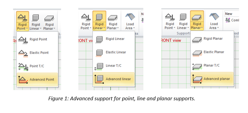
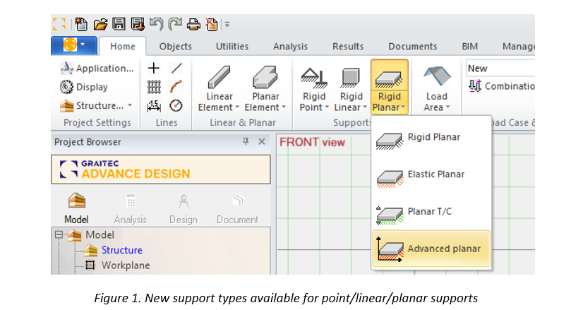
Advance Design has all these special supports available in the advanced supports feature. They can be assigned to each DOF separately and are available for point, line and surface supports (refer to Figures 1 and 2)
In addition to these supports, a user defined nonlinear support mechanism is also possible (“NL-Diagram” option in Figure 2).
2. Application examples
1.1. Gap supports
Two identical 2D frame structures are considered. A pin support is used on the left side and an advanced support on the right side for each frame (refer to Figure 3). Frame 2 carries double the load of frame 1.
The advanced support for both frames is fixed in the vertical translation and presents a 2 cm displacement gap in the horizontal translation (refer to Figure 4).
Since nonlinear supports are used, a nonlinear analysis is conducted and the results are presented in Figures 5 and 6:
In Figures 5 and 6, it is clear that for frame 1 the gap support did not reach its limit (1.67 cm < 2 cm) therefore no horizontal support force was applied to block the displacement. For frame 2, theoretically we should get twice the displacement since it carries double the load. However, the gap limit of 2 cm is reached and a horizontal support force is applied to block any further displacement.
2.2. Hardening supports
Considering similar frame structures to paragraph 2.1. A pin support is used on the left side and an advanced support on the right side for each frame (refer to Figure 7). Frame 2 carries double the load of frame 1.
The advanced support for both frames is fixed in the vertical translation and presents a 10 kN limit hardening support in the horizontal direction (refer to Figure 8).
Since nonlinear supports are used, a nonlinear analysis is conducted and the results are presented in Figures 9 and 10:
In Figures 9 and 10, it is clear that for frame 1 the hardening support limit is not reached (8.27 kN < 10 kN) therefore the support was able to block the displacement. For frame 2, theoretically we should get twice the support force since it carries double the load. However, the hardening support limit of 10 kN is reached and it can no longer block any further displacement requiring more than 10 kN of force.
3. Conclusion
The advanced supports are a powerful tool in Advance Design for modeling structures with particular support conditions. The user can choose between predefined support mechanisms such as gap and hardening supports or define his own mechanisms.
by Mateusz Budziński Structural Analysis Product Line Manager
Abstract
In this article, you will find out what geometry possibilities are available for selected Advance Design reinforced concrete modules – RC Beam, RC Column and RC Footing.
One of the characteristics of good and universal design software is flexibility in the range of supported geometry types. Indeed, what if our software allows a full range of analysis, if it supports only one or two basic geometric types. Therefore, Advance Design reinforced concrete element design modules offer a wide range of geometry types and a large range of their modifications. Let us take a look at the capabilities of 3 of the modules in this regard: RC Column, RC Beam and RC Footing.
RC Column
Advance Design RC Column module allows you to perform reinforcement analysis of reinforced concrete columns. One of the basic geometric settings is the selection of the column section. There are eight types to choose from:
It should be noted that the type and distribution of reinforcement in the elements shown in the above and next images are only examples, as in practice they depend on many factors (starting from the load, through the individual settings of reinforcement parameters, to the standard conditions for the given country).
In the case of RC columns, it is also worth mentioning the possibility of specifying the beams and columns above, which affects the configuration of the starting bars.
RC Beam
Advance Design RC Beam module allows you to perform reinforcement analysis of reinforced concrete beams. Apart from the possibility of defining a beam as a multi-span beam, the main geometry modification possibilities concern the cross-section as well as openings and depressions.
Let us start with the cross-section of a typical beam – a simple cast-in-place rectangular section.
The next types of configurations available are cross sections in which part of the section is prefabricated. We can define different types of configurations with prefabricated beams, slabs, and cuts.
There are also various possibilities for modifying the beam’s elevation, including the possibility of defining lower and upper depressions on any part of the span, as well as defining rectangular and circular openings.
As with all other types of geometry, even for such an unusual beam as in the image above, the reinforcement is calculated automatically, taking into account all standard requirements.
In addition, the RC Beam module enables the definition and analysis of corbels, which can have fixed or variable heights.
RC Footing
Advance Design RC Footing module allows you to perform reinforcement and geotechnical analysis of concrete isolated and continuous footings.
The basic possibilities of modification for continuous foundations are the ability to specify bevels, i.e. the possibility of obtaining a trapezoidal cross-sectional shape. In addition, we can freely modify the position of the supporting element (wall).
Finally, it is worth mentioning that in addition to modules for RC beams, columns and foundations, Advance Design also includes other design modules, including reinforced concrete walls and shear walls, which allow many types of geometry. But that’s a topic for a separate story.
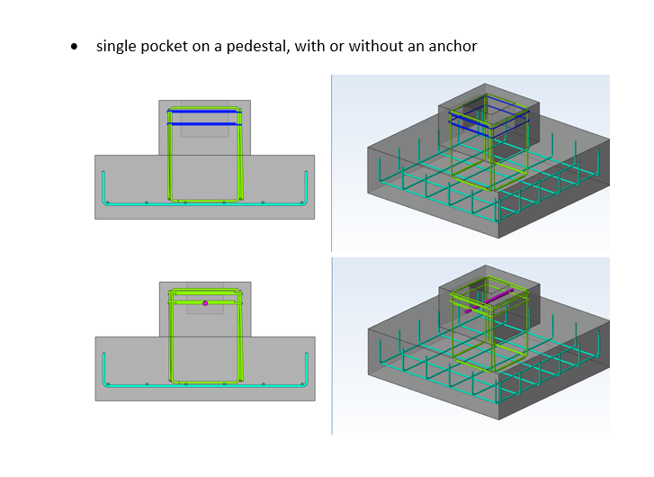
In this article you will see how our new Masonry design module can handle walls modeled in Advance Design.
Keywords: #AdvanceDesign #Masonry
Starting with Advance Design 2023 you can model and design Masonry Walls according to Eurocode, NTC and CR6 codes. In order to correctly cover full approach following novelties were implemented:
FEM calculations – in the definition of masonry materials (single/two-layer/re-layered, slotted hollow/filled);
FEM calculations – in the definition of rotary/translational edge releases, including single-sided compression/tension releases;
Design of walls defined in the FEM model in the new design module according to codes;
Design of walls in standalone design module application for a wall defined and loaded separately by the user (without the FEM model).
1. Definition of masonry material in Advance Design
Advance Design 2023 implements a new material family – MASONRY, along with reference to relevant national standards, for example Eurocode 6 together with national annexes. Within this family, it will be possible to define walls of various types in terms of their construction – single-layer (including stiffened), two-layer, façade, cavity walls (filled or not). The type of wall will affect the mechanical parameters of the material, such as the strength parameters of the wall, but also stiffness. Thanks to this, it will be possible to define multi-material walls and you will not have to worry about determining their parameters yourself. In addition, a database of masonry units and mortars was implemented.
2. Masonry design module in Advance Design
Due to the fact that the masonry dimensioning has been implemented in accordance with our current philosophy, 2 work scenarios will be available as a dimensioning module – the use of the module on elements in the FEM model as well as the independent launch of the application, where the user, by defining the geometry of the wall and loads, will calculate any part of the wall without need to create a complex FEM model. So far, other reinforced concrete modules such as beams, columns, footings, etc. have worked on the same principle.
When working with a masonry wall in Advance Design, the key is how to transfer this wall to the module – as you can see, all pillars can be designed within one element. Working with the module itself looks identical to the existing reinforced concrete modules.
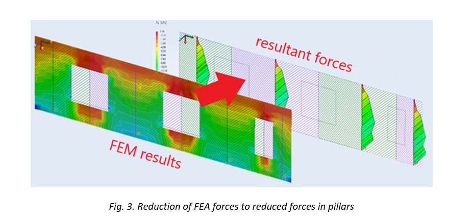
The method of determining the design forces is also interesting – strip method was used here, which was also used earlier as one of the possibilities of design RC slabs.
Thanks to this, FEM forces are converted into resultant forces reduced in the pillars. But importantly, the user will also be able to manage the width of the integral and enter their own panel division.
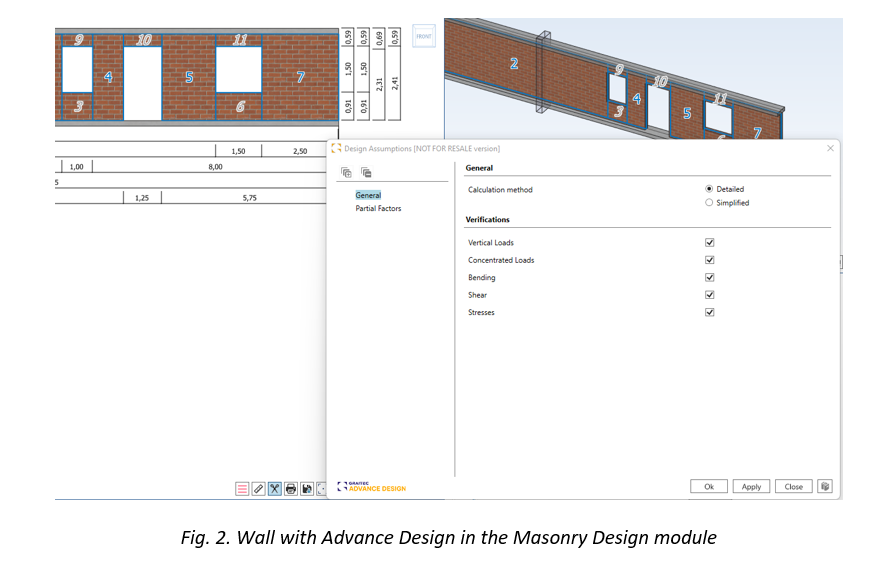
3. Masonry design according to Eurocode 6
On the basis of the above reduction or on the basis of external loads (in the standalone version of the module), the pillars are dimensioned according to the provisions of Eurocode 6 (or Italian NTC/Romanian CR6). Both detailed methods according to part 1 of the standard as well as simplified methods based on part 3 may be used.
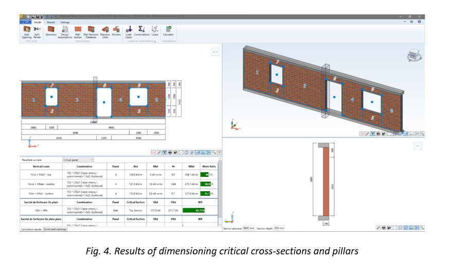
The external and internal walls of the basement floors, intermediate and highest, are designed.
The scope of calculation is the design of walls:
loaded mainly vertically
under concentrated load
for bending from loads perpendicular to the plane of the wall (e.g. wind/ground pressure)
for shear in and out the plane of the wall.
In addition, the stresses can be verified according to the classic principles of mechanics. The user will be able to indicate whether he wants to carry out all or only selected verifications, and the results will be presented for the worst or specifically indicated pillar.
This article is the second one in a series of 3. In this series, you will find basic information about Advance Design Steel Connection: what it is, how it can be used, and which are the main features of the module.
This second article will explain how to use the Advance Design Steel Connection module in the Advance Design environment.
Advance Design allows the creation of different types of connections between the steel profiles. Connections can be created in the modeling step and the analysis step as well. Advance Design also performs the connections errors verification. The verification function, available anytime during the modeling and also at the creation of the analysis model, displays in the command line the connections modeling errors and warnings (if any).
2. Create connections in Advance Design
The creation of the connections between steel members is very easy. Once the steel structure is defined the connections can be added.
The connection types are available in the contextual menu at the right click based on selection or the ribbon.
Connections – Contextual menu
Adding connections using the contextual menu, is done by selection. For example, if we want to add the base plate connection for all the columns, just select all the columns and choose the base plate from the connection list. This will instantly add all the base plate connections for all selected columns.
For an APEX connection selecte all the rafters and from contextual menu choose the corresponding connection: Connections -> Create on selection -> Fixed Connections -> Beam-Beam fixed connection
Therefore, in less than a minute the connections are created within the Advance Design model.
3. Group Connections in Advance Design
The option for Group connection is created to boost productivity and optimize the workflow.
To group the connections, select the connections you want to have in one group and do a right-click to access the contextual menu. From there choose the Connections -> Group.
More than that, the connections which are grouped will be renumbered to see from which group they belong.
4. Connection Design
Once the calculation is done, in the Design tab of the Advance Design Pilot, we can find the Connections. As you will notice, only one type of connection is available for design.
Before opening one of the connections and starting to design it, you must not forget to check the different options available for the Design Modules, including the Advance Design Steel Connection:
Based on the selected options, different loads and envelopes will be transferred to the steel modules:
Always transfer user-defined envelopes to Design Modules for steel connections elements
This option should be checked in case you have specific envelopes defined by you and you need them in the steel connection design
Export loads to design modules – Load cases and corresponding efforts diagrams/torsors
This option will export just the load cases and the corresponding efforts per load case.
Export loads to design modules – Load cases and corresponding efforts diagrams/torsors with the list of combinations
Besides the load cases and efforts, this option will export also the combinations.
Export loads to design modules – Load cases and corresponding efforts diagrams/torsors with the list of combinations + combination values of efforts diagrams/torsors
This last option will export also the combination values of the efforts.
An example of the MEP Connections will be shown further.
The geometrical configuration of the connection is similar to the standalone application but accessible from one single button on the ribbon: Geometry.
The Geometry button is regrouping in the Advance Design environment all the independent dialogs from the standalone application, in one dialog with multiple tabs.
The GUI of the tabs is identical to the one from the standalone module, offering the user the same smooth experience.
After the geometrical configuration is set, the Design Settings must be checked to make sure everything is according to the user project.
In the Design Settings, one particular option will define with which efforts the joints will be designed, the Combinations option. This option offers two possibilities: All Combinations or Envelopes.
All Combinations – the joint will be calculated with all existing combinations. Depending on the number of combinations, and in this case the number of connections grouped, the calculation can take longer than usual. For example, if we have 10 connections and 100 combinations, 1000 calculations will be performed.
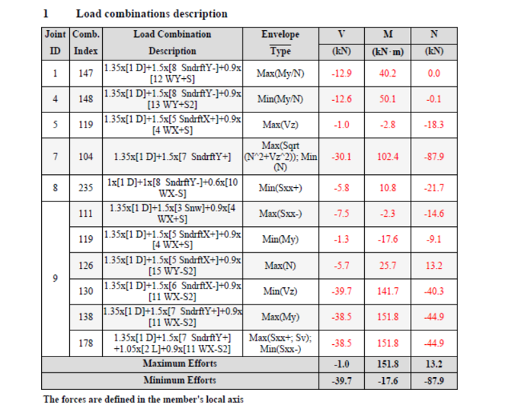
Envelopes – the joint will be calculated with the combinations that provide the maximum efforts. The criteria to choose these combinations are different from one type of joint to another and will be always available in the Report under the chapter Load Combinations description.
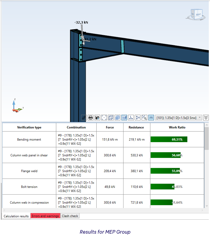
For the MEP group, we are showing in this article, these are the criteria and the corresponding envelopes used to verify all the connections from the same group. As we can see, instead of 100 combinations for each joint, we have only 11 envelopes.
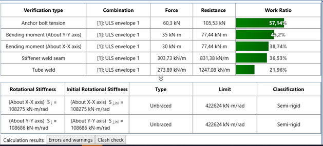
Once the Design settings are defined, the calculation can be run and the main results will appear in the console of the module. In case of warnings or/and errors, the corresponding tab will be highlighted.
If everything is ok, the drawing can be generated. This is done automatically while clicking on the Interactive Drawing tab available in the top left corner of the main window.
The report generation is similar to the standalone module. On the Ribbon, we have the Report Settings button, which allows the configuration of the content we want to have in the report. Here, the user can choose what chapters to include in his report.
Next to the settings, the Generate Report button is available. The report can be generated in PDF or DOC format, depending on the needs of the user.
This article is the first one in a series of 3. In this series you will find basic information about Advance Design Steel Connection: what it is, how it can be used and which are the main features of the module.
The Advance Design Steel Connection module is the evolution of a French local product Melody Attache. Even if today GRAITEC French customers are using the local product, because of the evolution of the software industry, Advance Design Steel Connection was born.
As I mentioned in a previous article, the Advance Design Steel Connection module has evolved over the years, the User interface has changed, and a wide variety of steel joints can be calculated according to the EC3 norm, in a fast way, efficiently covering many of the situations that can occur in the steel joint calculation.
This evolution of the module can be translated into an embedded application in Advance Design and a standalone application module. Therefore, when a user is installing Advance Design, the steel connection module will be available as well, within Advance Design or standalone.
Old Version of ADSC
Version 2023 of ADSC
2. What is Advance Design Steel Connection
The Advance Design Steel Connection module is a specialized and dedicated module for joint design, using analytical methods according to Eurocode 3. The module is part of the Advance Design application and can be run inside Advance Design and as a standalone application.
In my last article, I have presented all the connections available in the steel connection module, connections documented in Eurocode 3, with specific analytical methods. Let’s have a brief review of the connections offered by the design module: Base Plate, Tubular Base Plate, Moment End Plate, Apex Haunch, Clip Angle, Gusset, Splice, HSS Bracing, Gable Wall End Plate.
3. How to use Advance Design Steel Connection based on environment
The Steel Connection module can be run together with Advance Design, allowing the user to design the specific connection directly from the Advance Design model without exiting the application.
Another way to use the module is as a standalone application, allowing the user to design the one by one the joints.
A. The Standalone environment
After the installation of Advance Design, besides the icon of the main application Advance Design, a folder is created: GRAITEC Advance Design modules. Inside this folder, the Advance Design Steel Connection icon is available, to launch the standalone application.
Once the application is started, the starting page will appear from where the user can set up the Localization, create a New file, Open an existing one, or select a predefined template from the available list for Types of connections.
Start Page
After choosing a type of connection, the user can start to configure it as needed. The accessible user interface offers all tools needed to achive the requirements.
Example of joint in standaloane
Configuration dialogs – Geometry
Once the geometry is configured, the design assumptions, the combinations and the loads can be set using specific dialogs.
Configuration dialogs – Design assumptions and Loads
As everything is set the calculation can be lunched and the results can be check quickly using the results bar available in the bottom left corner of the application window.
Results on standalone
As any other design module from GRAITEC, the results and all the geometrical details, including loads, can be checked in a simplified or detailed report. Also, the report can be generated in a DOC or PDF file format.
Report settings
I must specify that the detail report contains all formulas and articles pointing to Eurocod chapters.
Here below we can see an example of the Compression resistance of the column verification. As you notice, the chapters from Eurocode are listed on the right side of the report, in line with the specific verification.
Compression resistance of the column
As I mentioned at the beginning of or the article, this is the first one in a series of 3.
Don’t miss the next one, where I will talk about how to use the steel connection module in Advance Design enviorement.
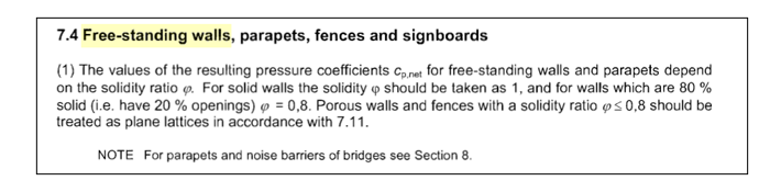
Free-standing walls are covered in §7.4.1 from EN1991-1-4.
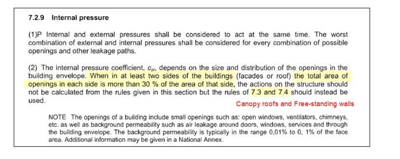
This part is intended towards fences as well as buildings with so many openings that they should be designed as per §7.3 (canopy roofs) and §7.4 (free-standing walls).
2. Theory
The Eurocode 1 defines two types of free-standing walls:
Without return corner
With return corner
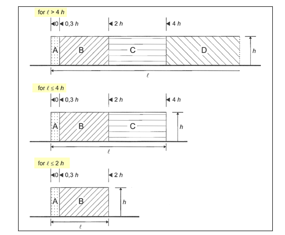
Free-standing walls will be divided in A, B, C and D zones, depending on how long they are.
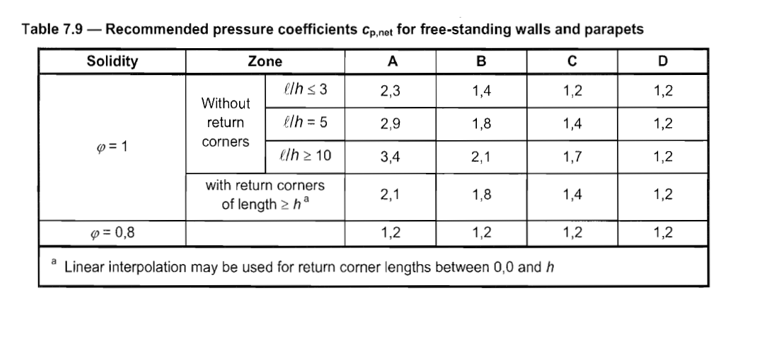
Pressure coefficients for each zone are determined from Table 7.9 and may require up to 3 successive linear interpolations based on:
The dimensions of the wall (Length/Height ratio)
The length of the return corner (if any)
The solidity ratio of the wall (also called opening ratio or porosity)
3. Example – Free-standing wall with return corner
Assume a free-standing wall (Length: 16m and Height: 4) with a 0,9 solidity ratio.
This wall has a 2m-long return corner.
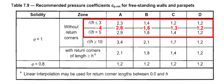
3.1. 1st linear interpolation We perform a 1st linear interpolation based on the length/height ratio of the wall (ignoring the return corner).
Yet, the values we have just obtained (in red) only stand for a wall without a return corner.
A 2nd linear interpolation is then required.
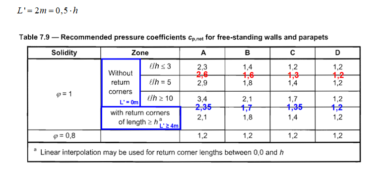
3.2 2nd linear interpolation
We perform a 2nd linear interpolation based on the length of the return corner (noted L’).
Yet, the values we have just obtained (in blue) only stand for a solid wall (φ = 1). A 3rd and final linear interpolation is then required.
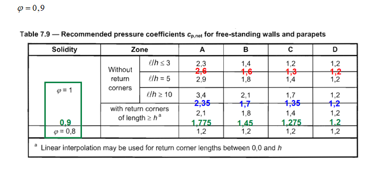
3.3. 3rd linear interpolation
We perform a 3rd linear interpolation based the solidity ratio of the wall.
The values we have just obtained (in green) are the ones we should expect for the A, B and C zones (the wall is not long enough to get a D zone).
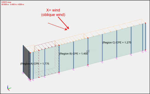
There are the values the climatic generator from Advance Design 2023 will return:
Of course, Advance Design will consider all required wind directions (perpendicular and oblique winds).
Advance Design will also consider more complex effects, such the potential force reduction that can be benefited from an upwind wall, through the shelter factor (ψs) defined in §7.4.2:
4. Conclusion
The estimation of wind forces on free-standing walls sure is a tedious process, with a high risk of errors due to the various linear interpolations needed.
Fortunately, version 2023 of Advance Design now handles these structural elements, generating the corresponding forces on your 3D structures in a single click.
by Mateusz BUDZIŃSKI Structural Analysis Product Line Manager
Abstract
In this article, you will find out what impact the changes made in the latest version of Advance Design have had on computation time.
Keywords: Advance Design, 2023 release, Performance, Calculation time
Introduction
The latest version of Advance Design brings a great number of changes and enhancements in many fields of the program. One of the most visible changes are improvements related to the speed of computation and the way data is stored. This short article will show the impact of these changes.
Description of changes
To help increase productivity time in Advance Design, we have worked hard to improve several areas, which translate into much faster calculation times, as well as reduced file sizes of the results.
Three areas have been changed:
Improvement of the calculation solver and program architecture
These changes consisted in the optimization of operations, thanks to which the speed of the FEM calculations has been increased.
Changed the way results for combinations are calculated
Previously, the results for each linear combination for each node were determined and saved to a file during the calculation. Now the results are calculated while displaying the results, which has dramatically reduced the size of the project on disk as well as significantly reducing the computation time. At the same time, the increase in the generation time for graphical results is unnoticeable.
Optimization of verification procedures for steel and timber elements
These changes concern the design procedures for steel and timber linear elements, resulting in a significant reduction in design time. Although some changes and improvements are common to all standards for steel and timber design, special attention has been given to design procedures for members according to Eurocode 3 and 5.
Examples
Below are 5 examples that illustrate the changes between the current and the previous version of the program regarding FEM calculations, steel/wood design and the weight of the result files.
The average increase in performance
The above models represent an approximate range. However, the effect is global and independent of the nature and size of the model. The table below, shows the aggregate results for the decrease in the required time, as well as the decrease in size of the project file compared to the previous version of the program for a sample of 15 various models of different sizes and computational range.
Note that the above values are averaged and may vary depending on the number and type of elements, the number of load combinations and the type of analyses performed. The smallest impact of changes is seen on smaller structures with a small number of combinations but complex types of analysis (for example nonlinear). The greatest benefits can be seen for large structures with a large number of linear combinations.
This article highlights the importance of construction stages in studying frame structures with transfer beams. For this purpose, a result comparison between Advance Design construction stages and classical full model single run analysis are presented for a steel frame model with a transfer beam.
Keywords: Advance Design, Construction Stages, Transfer Beam.
1. Introduction
In conventional structural analysis, all loadings are applied at once on the complete final structure before studying their effects in a single step calculation. In other words, no loading of any type is applied on the structure until the entire construction process is completed. However, in practice, structures are constructed in stages (story by story) and loadings such as self-weight, construction and finishing loads are present at each stage prior to structure completion. Therefore, at each construction stage, the distribution of displacements and internal forces in the completed parts of the structure (due to the existing loads) is not affected by elements of upper stories that do not exist yet.
Neglecting the construction stages effect in the classical analysis will sometimes yield wrong results. A good example where this effect should not be overlooked is in analyzing frame structures with transfer beams.
2.Frame structure with transfer beam
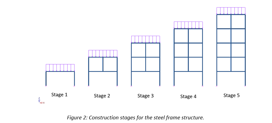
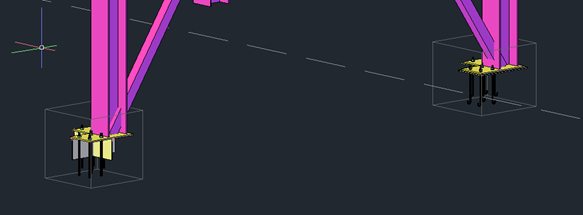
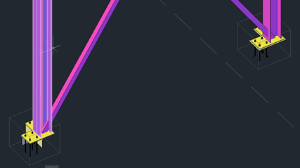
A steel frame structure with a transfer beam in story 1 is considered. This structure is subjected to its self-weight and finishing dead loads at each story (refer to Figure 1).
2.1. Construction stages
Construction stages are defined according to the actual story by story construction sequence (Refer to Figure 2).
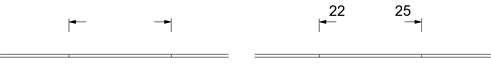
2.2. Results comparison
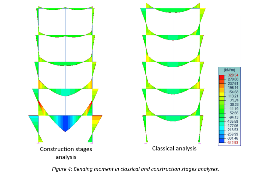
To highlight the importance of conducting construction stages analysis, results comparison between the Advance Design classical analysis (all loads applied at once on the complete final structure) and construction stages will be presented (refer to Figures 3, 4 and 5).
3. Conclusion
The real structural behavior obtained by the construction stages analysis is very different from the results of the classical analysis. Neglecting the construction stages effect, will lead to a dangerous under dimensioning of the transfer beam and middle column.
In this article you will see how to define a support of limited capacity for example a foundation piles.
Keywords: #AdvanceDesign #Concrete #Piles #FEM
1. New advanced support in Advance Design 2023
In Advance Design you could easily define rigid, elastic and non-linear (tension/compression) supports. Starting with 2023 release of Advance Design the possibilities increase with new more advanced support type. This new type will allow you to define more complex non-linear functions.
The definition of new supports is as it was before. However the restraints are specified differently.
Right now for each direction a different function can be defined. There are 3 linear restraints (free, fixed or elastic) and 5 non-linear where user specify a specific function.
2. Support with limited capacity
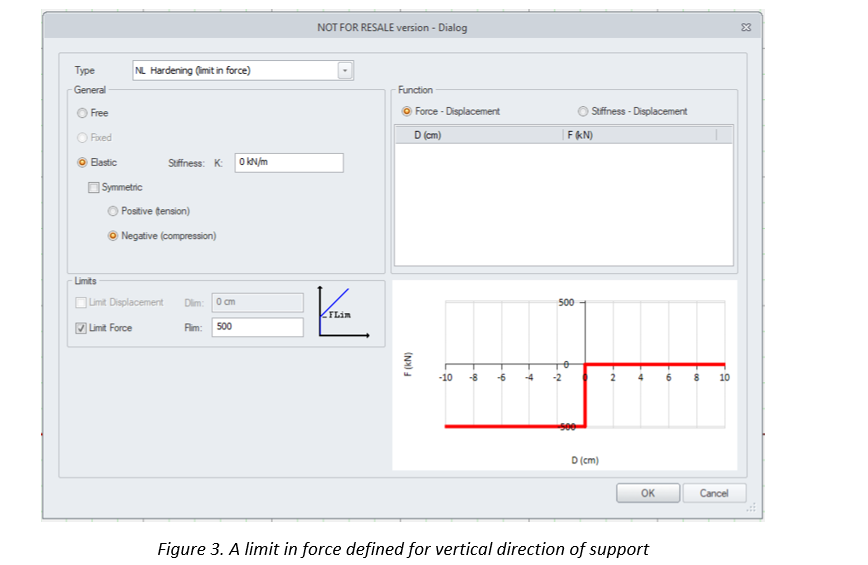
One of the example of non-linear support type is ‘Hardening’. For this support user specify a limit in force after which supports reaches it capacity.
Above you can see a support that is rigid until reaching the limit in force of 500kN. After reaching it capacity the support weakens and has reduced stiffness – its not rigid anymore. The restraint become free or elastic if any stiffness is defined.
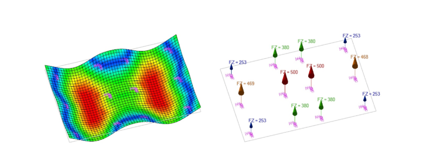
Please see this simple example below of a foundation slab supported by piles of capacity 500kN.
When external loads are of low value piles do not reach the capacity limit. All works with the same rigidity.
But with increasing the loads some of supports reach the limit. Deformation changes because 2 middle piles can’t take any more load. The forces are distributed to neighboring supports.
With further increasing of loads more and more piles reach 500kN support force, until point of the slab being unstable.
3. Summary
As you can see this new support type will allow you to perform more advanced and complex analysis, and cover a bigger spectrum of design needs.
Note that limit in force is only one of the possibilities. Thanks to non-linear diagram definition user can reflect any behavior of structure support.
In Advance Design, we can quickly and efficiently perform the entire design process of a building structure, from modelling to analysis and structural optimization. And an integral part of the design process is the review, evaluation, and documentation of the calculation results. Today we will look at one aspect of this – methods for viewing results from FEM calculations using values in tables.
Available methods of presenting results with using tables
Results in tabular form can be generated in two ways – by generating tables during report generation, or using a new mechanism introduced in the latest 2023 version, by generating tables with results directly on the screen. Let’s look at the two methods in turn.
Report tables
One of the main components of calculation reports are tables with results. The selection of the template tables that are to be included in the report is made on the Table tab of the report generator. In case of FEM analysis results, the number and type of available table templates depends on the model, including the type of calculations performed. For example, if no surface elements have been defined in the model, then no templates with results tables for surface elements will be found in the list
However, before we start to generate a report with a table, especially in case of results from FEA results, it is crucial to properly narrow down the range of results to be viewed. The reason is very simple – the number of results can be huge, especially when we have a larger model and a large number of combinations. In addition, most tables, such as the internal forces table for linear elements, present results at each node by default. With a relatively dense division into finite elements, this can result in a table that is many pages long for a single beam. So how do I filter the report tables?
Let’s start by selecting load cases / combinations. This can be done directly in the generator window using the load cases / combinations filter window. Thanks to the convenient selection options, we can easily set the range of interest. The selection made in this way is common for all tables for which you are generating the report.
However, if you want to select a different case range for some tables, then you can filter using the properties dialog box for each such table.
This way is also used for selecting points in which the results are presented. We can increase or decrease the result point density by selecting one of the options from the list. For example, in the table of internal forces of linear elements, by default the results are displayed in nodes of finite elements. We can change this setting so that the results are presented at 3 points – at the beginning, middle and end of the member, for example.
To have the table contain results for only selected objects, we can also use the table properties dialog box to generate a table for only the items in the selected systems. But we can also easily generate a table for any range of objects, even for a single element. To do so, before generating a table, you should simply select the elements for which you want to generate a report.
Another important functionality is the ability to create your own table templates. It means that we can decide what information and results should be placed in particular rows and columns of the table. We can put different types of data and results in the same table, of course within the same element type (for example, a linear element). Such templates can then be used to generate tables in exactly the same way as the default templates.
Tables with results
In Advance Design 2023, we have the ability to filter and check FEM calculation results even faster. This is all thanks to the new “Results Tables” functionality which allows us to quickly display the results in tabular form directly on the screen. This feature is available after the FE calculation has been completed and can be accessed directly from the ribbon.
We can generate tables using default template list, and if we want to narrow the number of displayed columns, we can easily hide the unnecessary.
But we can also create our own template with specific result columns and settings. For this purpose, a similar mechanism and dialog box is used as when defining report table templates. Saved table templates will be able to be used in all projects or deleted when no longer needed.
Similar to the report tables, you can narrow the table content to show results for only selected objects as well as for only selected load cases/combinations.
The tables also have useful features that make it easier to find interesting results in the already generated table. For example in an easy way we can sort values on columns, just by double clicking on headers. And we can filter the results using special fields below column headers. We can use text filters but also different types of single and multiple value ranges. And what is great is that we can easily use multiple filters at the same time.
Finally, another great feature of the tables is the ability to export of the contents of the table to an Excel spreadsheet. To do this, just use the export button and the whole process will run automatically. This allows us different scenarios for further external work with results.
In this article, we will apply the methods from EN1996-1-1, Annex C to estimate the out-of-plane eccentricity of loading on a masonry wall subjected to mainly vertical loading.
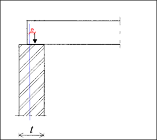
The vertical load coming from a floor connected on top of a masonry wall is usually eccentric.
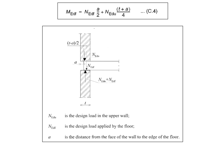
As a result, this eccentric force will create an out-of-plane moment on top the wall that must be properly assessed. Annex C from EN1996-1-1 provides two methods in that regard. In this article, we will apply each method on an example, and we will compare the obtained moment.
2. Moment on top of the wall
Annex C from EN1996-1-1 provides two methods to assess the out-of-plane moment on a masonry wall:
First method, in Clause (2), is based on the stiffness of the connected members (floors and walls)
The other method, in Clause (6), relies on a simplified expression
Although quite intimidating, the method based on the stiffness of the connected members from eq. (C.1) is said to be less conservative and therefore, more cost-effective.
We will compare both methods on a given example.
2.1. Assumptions
We will calculate the moment on top of the lower wall in the configuration below:
Walls
Thickness: t = 0,2m
E = 3192 MPa
Level height: H = 2,70m
Boundary conditions: Fixed
Slabs
Thickness: t = 0,2m
E = 30 000 MPa
Clear spans: L = 6m and 2,5m
Boundary conditions: Fixed
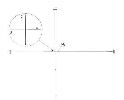
2.2. First method – Stiffness of the connected members
The first method uses a simplified frame model where members 1 and 2 respectively stand for the upper and lower walls, while members 3 and 4 stand for the left and right floors.
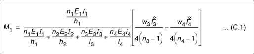
Moment is then calculated from eq. (C.1):
Where:
h1 and h2 are wall heights
l3 and l4 are the clear spans of the connected floors
w3 and w4 are the distributed loads on the adjacent floors
ni are the stiffness factors of each member (taken as 4 for members fixed at both ends and 3 otherwise)
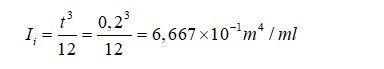
All inertias are equal due to all members having same thickness (0,2m):
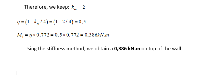
Eq. (C.1) can then be simplified:
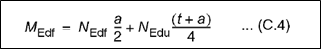
2.3. Second method – Simplifed expression
The second method relies on a simplified expression
In case of an intermediate wall, with floor spanning on each side, the load from the wall above (NEdu) is considered to be concentric and each side of the floor is taken as supported individually by half of the total bearing length (a = t/2):
3. Conclusion
The method based on the stiffness of the connected members from Clause (2) appears to be less conservative indeed.
Yet, the gain turns out to be minimal most of the time.
Therefore, the simplified expression from Clause (6) is usually the preferred method, especially for manual calculation.
Fortunately, our upcoming Advance Design module, dedicated to masonry wall design, will instantly apply both methods and retain the minimum moment value, ensuring an optimum design for your masonry projects.
The Advance Design Steel Connection module has evolved over the years, the User interface has changed, and a wide variety of steel joints can be calculated according to the EC3 norm, in a fast way, efficiently covering many of the situations that can occur in the steel joint calculation.
Part of Advance Design, the Steel Connection module ensures the configuration of a seamless solution, with the ability to manage and calculate bolted and welded joints, and with fully detailed design reports that include the calculation formulas and reference to the design code.
The joint library from Advance Design Steel Calculations is categorized according to the connection type, therefore 9 categories are available.
Type of joints
The Steel Connection module comes with predefined configurations for all categories, configurations that can help the user achieve faster the desired configuration.
1. Base Plate
The Base Plate joint is created by welding a steel plate to the bottom end of the column that is connected to the foundations through anchors. The joint can include several reinforcement plates, shim plates, or shear anchors.
The joint has predefined configurations that are categorized as:
Reduce base plate
Pinned base plate
Fixed base plate
Pinned base plate
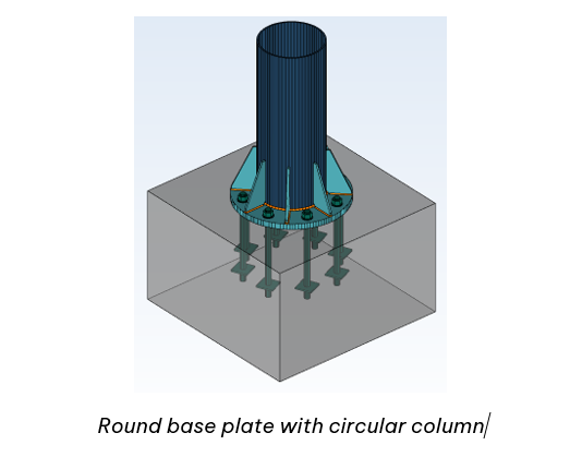
2. Tubular Base Plate
The Tubular Base Plate is created for cases when the column has a hollow section, rectangular or circular. The particularity of this connection is that the verifications are done in two directions, therefore the joint can be categorized as a 3D connection.
For this joint, 3 predefined configurations are available:
3. Moment End Plate
Moment End Platejoint of Advance Design – Steel Connection module is used to connect a beam to a column flange. Additional elements are available to customize this connection (i.e. haunches, plates, stiffeners, welds).
4. Apex Haunch
Apex Haunchjoint of Advance Design – Steel Connection is used for roof beams. It consists of two beams spliced with bolted end plates, on which haunches or plates can be attached at the top/and the bottom. The haunches are created from profiles or plates.
The connection has 2 predefined configurations: with or without external bolts, but the many other possibilities are achievable.
5. Clip Angle
Clip Angleconnections are used for connecting a floor beam to another beam, or a column to a beam. The attached beam can be sloped to the main one. The angles are bolted or welded to the main beam.
The connection of the module has 5 predefined configurations which can be changed accordingly to the project needs. Besides those, models can be started from the default configuration and modified.
6. Gusset
Gussetconnection of Advance Design – Steel Connection module connects bracing members using gusset plates. The number of bracing members that can be enabled can vary from one to three. For the calculation, the Advance Design – Steel Connection module implements Eurocode 3 international design standards, for all the connection components verification and parts of the connected elements.
7. Splice
Splice connection of Advance Design – Steel Connection module is often used to assure continuity for structural members (beams or columns) along their length. The splice plates can be bolted or welded to the main members. On web connections, U-shaped profiles can be used instead of splice plates.
8. Gable Wall
Gable Wall End Plateconnection is used to connect a continuous beam to the top of the column. Similar to the Moment End Plate joint, additional elements are available to customize this connection (i.e. haunches, plates, stiffeners, welds). Like all the other connections, the Gable wall has some predefined configurations which can be changed according to the needs, or the default configuration can be initialized and changed as needed.
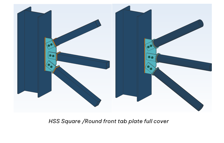
9. HSS Bracing
HSS Bracing connection of Advance Design – Steel Connection module connects bracing members with hollow sections, circular or square. The number of bracing members can vary from one to three.
As a connection from the module, it comes with 6 predefined configurations to help the user achieve faster the needed configuration.
Graphical presentation of results for surface elements
Advance Design can generate and calculate various types of three-dimensional structures, including those containing flat surface elements (such as slabs or walls), as well as shell elements (e.g. curved roofs or circular tanks). In addition to the preparation of the model and the execution of the calculations, an integral part of the design process is the review, evaluation, and documentation of the calculation results. Today we will look at one aspect of this – the ways in which results for surface elements are presented graphically in Advance Design.
Model
The available methods will be presented on the example of one slab of a very simple spatial model of a concrete structure.
Figure 1 : Model in Advance Design
For the selected load case, we will check the graphical presentation of the displacement results, but the same methods as presented below can be used to display other types of results, ranging from internal forces and stresses to outputs related to the design of reinforcement (for example reinforcement areas or crack values).
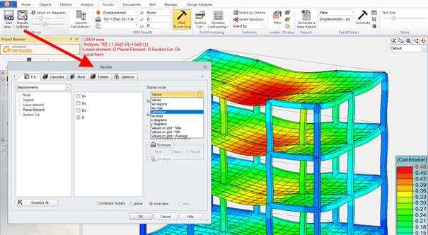
How to change display settings for results
With the model calculated, displacements for all or selected part of the model can be displayed directly using the commands available on the ribbon. The results are then presented using a default display mode – in the case of displacements this is called ‘Deformed’. To change the mode, use the window with the setting of graphic results (opened, for example, using the keyboard shortcut Alt+Z). Note that the list of available display modes depends on the type of element and the type of result. In the case of surface elements, a list as shown in the image below will be available.
Figure 2 : Changing display styles
Available display modes
Let’s now take a look at the display modes available. The default one is called ‘Deformed’ which presents the results as color maps on the deformed structure. This mode is available also to linear elements, which allows showing results for a whole structure using common color scale.
Figure 3 : Deformed
There is a twin mode, called ‘Iso regions’, which also shows the results as maps but only for surface elements. The iso-value regions represent colored polygons on the planar elements corresponding to certain results on displacements, forces, stresses. Thus it is possible to view the highest stress areas on the planar element within a single glance. The values of these regions can be smoothed or not; for this purpose you can use the option “Smooth results on planar elements” from the Results dialog box – Options tab.
Figure 4 : Iso regions
The next display mode is called ‘Iso lines’. The color of iso lines correspond to the results color scale. Note that regardless of the selected style, additional presentation options can be set, such as visibility of the finite element mesh, display of extreme values or values corresponding to particular iso lines.
Figure 5 : Iso lines
The next display mode is called ‘Iso maps’, which combines the display of isolines and solid color maps.
Figure 6 : Iso maps
As mentioned earlier, we can control additional graphical settings. In the example below, we have the same display mode but with isolines turned off and values displayed in finite element centers.
Figure 7 : Iso maps with values
The next two similar display modes are called ‘X Diagram’ and ‘Y Diagram’. These are diagrams in the X or Y direction of the local system respectively, displayed in a plane perpendicular to the surface element. As these diagrams pass through the centers of the finite elements the resulting effect depends on the density and shape of the mesh.
Figure 8 : Y diagrams
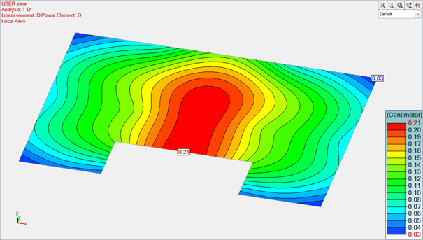
The next display mode available is called ‘Values’. And as the name suggests, it displays values in finite element centers. Depending on the settings the values can be displayed in scale colors or in solid color.
Figure 9 : Values
As the values can be difficult to read (too small or overlapping) in the case of a dense or irregular finite element mesh or at lower magnification, we can display the values using another style called ‘Values on grid’. This display mode comes in three variations – for presenting minimum, maximum or average values in a grid. The results grid is a virtual mesh of regularly arranged rectangles used only for the presentation of results. The setting of the mesh size is available individually in the properties of each surface element.
Figure 10 : Values on grid
Additional settings
In addition to the presentation display modes, Advance Design offers various additional options for setting the presentation of the results. Firstly, we can control the color scale. For example, we can set a reduced number of ranges with defined limit values.
Figure 11 : User scale
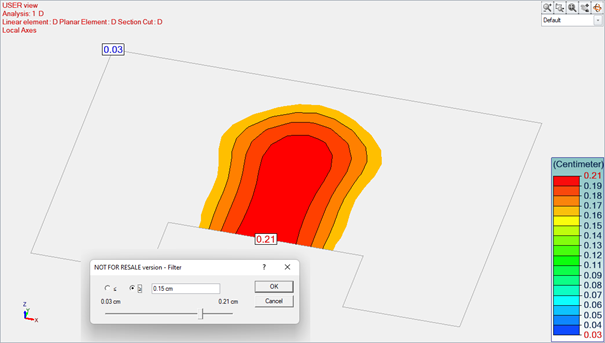
Another possibility is the presentation of results using Dynamic Contouring command. This allows you to filter the displayed values to a selected range.
Figure 12 : Dynamic Contouring
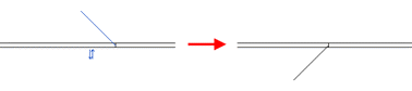
Another way of presenting results for surface elements is to display intersection diagrams. These are created using linear Section cut objects. You may create section cuts in the modeling step and in the analysis step, and like all elements of the model, the section cuts may be selected, resized, moved using CAD tools. Diagrams on section cuts may be generated in the element plane or in a perpendicular plane.
Figure 13 : Section cuts
Finally, it is still worth mentioning that for planar elements it is possible to view the forces and stresses results expressed in the main axes. For this we use dedicated display mode called ‘Main axes’. The two main axes are represented graphically by their color, the sign is represented graphically by the arrowhead direction (inward for negative values and outward for positive values) while the angle of axis orientation is given by the alpha values.
Figure 14 : Vectors (for internal forces in main axes)
Masonry can effectively carry compressive forces but this material only has moderate capacity when it comes to shear.
Yet, masonry walls may be exposed to wind forces that could cause shear failure mechanisms, especially on the top levels, where the compressive forces are moderate.
Therefore, shear resistance of masonry walls must be properly assessed.
Eurocode 6 provides a method in that regard.
2. Sliding shear resistance of an unreinforced masonry wall
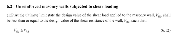
Unreinforced masonry walls subjected to shear loading are covered in section 6.2 from EN1996-1-1.
As usual with the Eurocodes, a design force (VEd, design shear force) is compared to a resisting force (VRd, shear resistance).
2.1. Assumptions
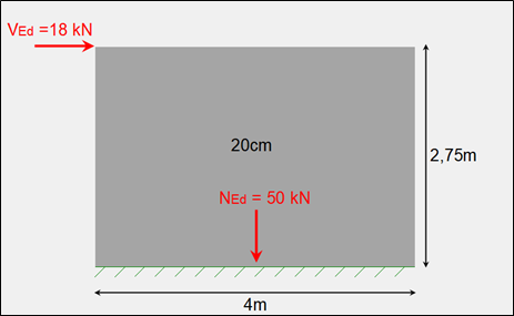
Assume the following wall:
Material characteristics
Initial shear strength: fvk0 = 0,20 MPa
Compressive strength: fk = 5,00 MPa
Partial factor for material: γM = 2,2
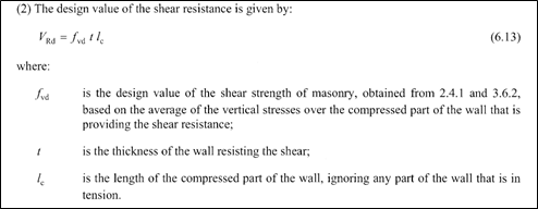
2.2. Shear resistance VRd
Shear resistance VRd is defined in eq. (6.13).
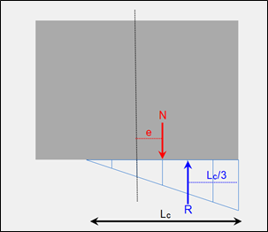
First of all, we need to estimate the compressed length of the wall (lc).
The VEd lateral force is indeed creating an in-plane moment that can cause tension at the bottom part of the wall, especially if the compressive forces are low.
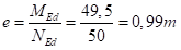
Moment at the bottom of the wall
Eccentricity
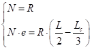
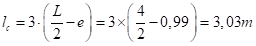
Compressed length lc
The eccentricity exceeds 1/6 of wall length.
Assuming a linear distribution and based on the equilibrium of force and moment:
We can assess the length of the compressed part of the wall:
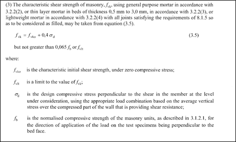
Shear strength fvd
Assuming all joints (vertical and horizontal) are filled with mortar, we compute the characteristic shear strength fvk with eq.(3.5).
The design compressive stress σd can slightly increase fvk.
Then:
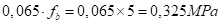
fvk does not exceed
The design shear strength is then given by:
Shear resistance VRd
We can finally compute shear resistance VRd from eq. (6.13):
Sliding shear verification:
The sliding shear verification is passed.
3. Conslusion
This verification can prevent some of the shear failure mechanisms that may occur in masonry buildings.
Of course, hand calculation might be tedious.
Fortunately, our upcoming Advance Design module, dedicated to masonry wall design, will perform this verification, among others, in a matter of seconds and provide a detailed calculation report, with intermediate values and reference to the EN1996-1-1.
by Stevens Chemise Product Line Manager at GRAITEC
Abstract
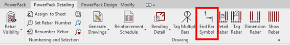
PowerPack for Revit propose an End Bar Symbol command, available on the Detailing ribbon. It allows for a quick definition on 2D views a special symbol showing location of ends of straight bars
PowerPack for Revit propose an End Bar Symbol command, which is useful especially for cases, when rebars overlap on the view to clarify reinforcement drawings.,
The End Bar Symbol command supports two usage scenarios:
called with existing rebar selection – symbols are defined automatically at both ends of selected bars,
called without any selection – a symbol it is defined at the end which is closer to the indicated point on the bar.
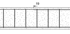
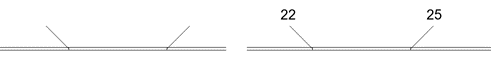
The type of bar end symbol depends on the family used (Detail items category). The default family and type are selected in the Reinforcement Configuration window.
The family supplied with the program (Graitec EndBarSymbol) contains two types of symbols:
tick (with or without bar mark annotation)
tag (with or without bar mark annotation)
This family also allows for easy configuration of the size of the components as well as easy flipping
by Kamil Dziedzic Solution technical specialist at GRAITEC
Abstract
In this article you will see how to define a multi-span concrete beam in Advance Design in order to design and detail it using RC Modules.
Keywords: #AdvanceDesign #Concrete #Reinforcement
1. Defining beams in Advance Design
In Advance Design you can model very different types of objects including planar and linear elements, which will represent our structural elements such as beams, columns, walls and slabs. With defining right section and material we can simulate behavior of our structure using FEM analysis.
If it comes to concrete beams we always could provide linear element stretching from one support to another. If we defined also intermediate supports like columns or walls our beam would be treated as multi-span.
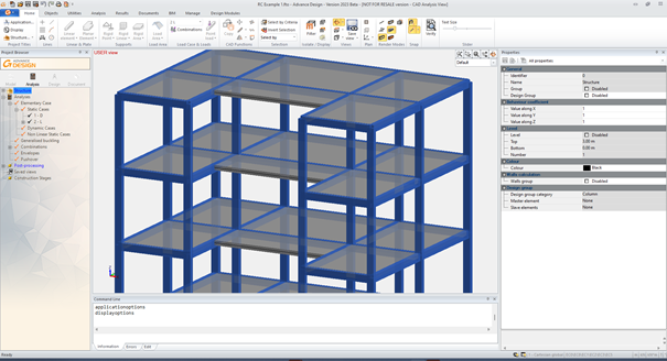
Figure 1. Beam as a linear element in FEM model of Advance Design
2. Super-element concept for RC design
Even though we could easily design a beam shown on figure 1 above this approach has some limitations. Because it’s a single element we can for example specify only one section height for all spans. However, sometimes we need for a different spans to have different sections due to capacity requirements or some technical aspects (such as need of clear height of a story, leaving some space for ducts and so on).
Starting with Advance Design 2022 it is possible to use super element concept also for RC design. Initially it was implemented for steel structures, however using this workflow was found effective also for other materials.
2.1. Creating a super element in Advance Design
To create a super element we model each span of a beam as a single element. Remember to always define them from support to support. If possible, try keep local axes in the same direction and orientation.
Last thing to do is to convert these 3 single linear elements into one super element. We can do that using context menu at right mouse button or finding these exact options on Objects ribbon.
Figure 2. Defining a super element of 3 linear elements
Note that now you can pick whole super element by selecting any part of it. However if you need to select only a single span for example to change its section you need to toggle pick mode from super elements to elements. You can do it by pressing ALT+E or again find it at right mouse button context menu.
Figure 3. Super element properties
After defining a super element you can see it has now new own identifier, a list of elements which you can always edit if needed and also each element included in this group gets a postscript to its name informing user it’s a super element. Remember you can always cancel super element similar way you created one.
2.1. Design of multi-span beam defined as super element
When you are done preparing super elements, rest is as usual. We need to perform a FEM analysis calculations to obtain static results. Now we are ready to open a super element using RC Beam Module.
Notice that super element shown below has 3 spans of 3 different sections height.
Figure 4. Opening super element with RC Beam Module
Right now we need to specify requested reinforcement and design assumptions. Element will be designed as it was continuous multi-span beam. Reinforcement drawings and schedules also can be provided for whole element at once.
Figure 5. Design of super element RC beam with Advance Design Module
Often in the steel structure detailing projects, we have the situation when the same type of connection is available, but with a different configuration, even if we talk about one parameter. Even if the configuration is different, the detailer might need to change one or more common properties of those connections.
Today, in Advance Steel this is possible with the functionalities around the “Group joints” feature, but with certain limitations. The limitations are related to the fact that the joints must be the same type and have identical configurations (master and slave behavior)
2. Joint Multi-Edit
The Joint Multi-Edit available with GRAITEC PowerPack for Advance Steel is allowing the user to change parameters in two or more joints from the same category but with a different configuration. The joints do not need to be grouped or have any master and slave behavior.
2.1. Criteria:
The criteria to enable this feature is to select 2 or more joints with are part of the same category: Base plate, Corner Base Plate, Gusset plate at 1, 2, 3 diagonals, Create Stiffeners, etc.
2.2. Example:
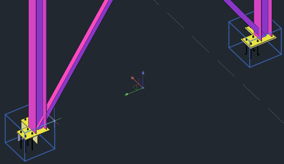
Following, to understand better how this feature can be used, an example with the Corner Base Plate joint will be explained.
Two columns with the Corner Base Plate joint are created but, as it can be seen, the configuration is different:
Different anchors
Different base plates dimensions
Shear lug enabled or not
Leveling plate enabled or not
Figure 1: Lateral view
Figure 2: Top view
To access the command Joint Multi-Edit:
Select both joint boxes
Figure 3: Selection of joint boxes
Right-click to open the active menu and search the “GRAITEC PowerPack Joint Multi-Edit” command
Figure 4: Right-click menu – command Joint Multi-Edit
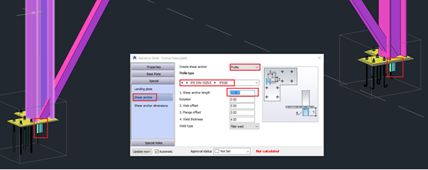
When the command is selected, the dialog of the joint will be displayed.
Note: The configuration of the last joint selected is the one displayed in the dialog when this is opened with the Joint Multi-Edit command.
Figure 5: Configuration of the last selected joint
Now, when any parameter is changed, the change will be propagated to all selected joints for which the multi-edit command was activated.
Figure 6: Changes’ propagation – Shear lug type
Figure 7: Changes’ propagation – Base plate dimension
The command is working with any joint category from Advance Steel as well as on any joint from the PowerPack.
Mateusz BUDZIŃSKI Structural Analysis Product Line Manager
Abstract
In this article, you will learn how to start modifying and defining your own drawing style template in Advance Design modules.
Keywords: Drawings, Advance Design Modules, Bar schedules, Templates
Modifying Drawings in Advance Design Modules
The reinforcement drawings generated by Advance Design modules are highly customizable. The range of possibilities is very large and can be divided into two groups – the current modifications that can be done to the generated drawing and the modifications to the templates used for generating the drawings
Current modifications to the drawing are mainly done graphically or using a series of simple commands available from the properties list. Among these are ability to modify the scale, change the position of views on the sheet, add/remove views (as new sections), rename views, add dimension lines, move descriptions or symbols.
The second group of modifications relates to the templates used for the generation of the drawings. There are many different types of templates available, starting from the most general Drawing Style, which is a template collecting all settings and layouts of views, through templates controlling the settings of colors, lines and symbols used, templates for title blocks and templates for rebar lists.
Today we will look at modifying the general drawing template – the Drawing Style.
Drawing Style – general information
The style template is the most general template and contains a complete description of the drawing, i.e. the orientation of the paper, how many and which views you see, their scale and position on the sheet, used drawing templates, title blocks and bar schedules.
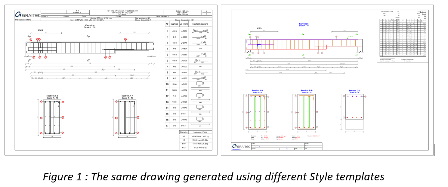
Each module (e.g. RC Beam, RC Forting, …) has its own set of style templates and their number and content is different depending on the regional settings of the program. So drawings may look different according to the default templates for France and the UK for example. However, anyone can easily modify existing templates or add their own.
Changing Drawing Style
Let’s start with how to apply a style other than the default template. The easiest method is to right-click on the first item in the tree (Drawings) and select one of the styles from the available list – Apply Style.
The list shows the styles available in the default styles folder for the given element type and for regional settings (country). By selecting ‘Select styles’ you can preview the contents of the folder and select a file from another location. This command menu also includes a Save Style command that saves all current drawing settings to a new Style template file.
Layout of views
Most of the changes to the settings in the property list (including the sheet format or the type of reinforcement list) as well as the number and type of views are written directly to the template. However, the placement of views and their scale depend on the Layout of views settings. So it is usually not enough to move the contents of a view (for example, a beam cross-section) to a new location on the sheet, but to move its associated rectangular outline, which is presented as a blue frame. Namely, modify the layout of the views on the sheet
To check and modify the layout of the views in the current drawing, right-click and select Edit Layout command.
We will then see the layout of the views, which we can freely arrange on the sheet by moving the corners of the outlines (using grips). This will allow us to ‘anchor’ a given view on the sheet, also in relation to the other views.
By default, the views are generated according to the position of the layout frame as well as their scale is automatically adjusted to its size. But we can change these settings using two options from the view properties.
The ‘Views fit layout’ option is responsible for automatically scaling the view so that it fits optimally in the frame area. If you disable this option, the scale will not be automatically modified when regenerating the drawing.
The ‘Views follow layout’ option is responsible for the location of the view relative to the frame area. If you disable this option, the view will not automatically follow the frame area when the drawing is regenerated, i.e. the last position of the view after it was manually modified will be preserved.
The above description, of course, only briefly introduces the subject of template customization, so I recommend exploring the available options on your own. At the end, one more note – remember that the final effect, i.e. finally generated drawings, can also be saved directly in DWG format, allowing further changes or assembling drawings in CAD if necessary.