May and June editions of Roof & Facade Asia,present the versatility of ADVANCE Steel for easy fabrication and erection at site without any errors, either with or without AutoCAD.
Historically based on AutoCAD, Advance Steel is the software solution 100% dedicated to steel construction. It can accelerate the design phase by offering an extensive library of smart objects, automatic joints and specific tools for creating standard structures, stairs, railing and miscellaneous steelwork.
In 2012, the standalone version was released, offering users the possibility to select the desired CAD platform, thus using the software with or without AutoCAD.
May edition of Roof & Facade Asia magazine has a case study for the ADVANCE Steel software solution, used directly on the AutoCAD platform, in the making of Valenciennes Stadium, in France. In short, ETI started using AutoCAD® to draw the firstlines of the project in 2D and submit it to thecontracting owners. The project owner’s and architect’s need to view more precise details in3D the most complex assemblies required the use of Advance Steel, which has a BIM approach. Advance Steel enabled fast modeling of all steel structural elements. From the 3D model, Advance Steel allowed the automatic creationof all fabrication and assembly drawings, with all the necessary labels and dimensions for the workshop.

So, was this easy for ETI? Surely not. The size of the project required four people working full-time on it: one Project Manager, Mr Fabrice Grisot, one Construction Engineer, Mr Stéphane Dottori, and two draftsmen. In order to follow the architect’s wish to have no visible bolts on the structure once the construction is erected, ETI had to design assemblies early from the study phase. Thus, bolted assemblies were designed to ease the transport of parts (that can reach a weight of 10 tons each) and the parts were welded together at site with fastening plates. The welds were then painted and grinded to get a perfect aspect. Therefore, it was necessary to model many weld preparation chamfers on the edges of the plates and the profiles to get a realistic result and, most of all, for these elements to appear clearly on the fabrication drawings.
But was it error free? Certainly seems like it…Mr. Stéphane Dottori, Construction Engineer for ETI Design Office later declared: “We did not receive a single phone call from the site foreman to report any error!”
Well, how great is that!? All the tools are provided for fast and efficient modeling either in 2D or 3D, depending on the user’s preference, subsequently creating all project documents (drawings, lists, NC files), covering every step, from structural modeling, to drawing creation, document management, up to manufacturing and fabrication, with no risk of errors.
So, if the union between AutoCAD and ADVANCE Steel offers so many benefits, why would a Standalone version be better?
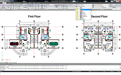
First of all, the Standalone version of ADVANCE Steel has many improvements and innovations in functionality, graphics and drawing quality. Second, it features the very well known ‘Ribbon’ interface, for model ‘creation’. Of course, so does AutoCAD, even with a more polished appearance and hosting the Advance Steel commands to the right of its standard tools, while the standalone version stores the most commonly used commands in the home tab, with more advanced features available further along the ribbon.
But in terms of display modes, the Standalone version “features basic wireframe and flat shaded”, while AutoCAD has a more advanced real time display mode. AutoCAD users will benefit from the ability of the platform to quickly model particularlycomplex curves. “While it is possible to do advanced compound geometry in the standalone version, it will be much quicker to do this in the full AutoCAD.”
So, is the standalone version still a competitive and advanced tool for customers? We hope so. Advance Steel’s ability to make lightwork of complex detailing tasks such as stairs and railings, means there is much potential and also still room for improvement.
Most of all, receiving the advanced features of AutoCAD and at the same time, shaving $4,000 off the overall cost by using Advance Steel Standalone is pretty hard to ignore. For existing AutoCAD users, the learning curve for the Standalone version is very fast, benefitting from good interoperability, built-in rendering tools, good 3D navigation tools and DWF available for design/review and sharing data over the web.
“At the core of the product there is little difference between the two versions. Layers, XREFs and other AutoCAD features are all supported in the standalone version and the workflow inside the products is virtually identical” – June’s edition of Roof & Facade Asia magazine states.
Here you can dowload the pdf version of the article appeared in June edition of Roof & Facade Asia magazine


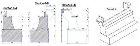
 The article describes how we can create reinforcement and formwork drawings for structures with a complex geometry, namely bridge abutment using


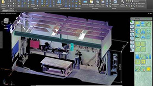
 A reinforcement bar distributed in one view will automatically be available in all views, as long as the 3D power option is activated in the reinforcement drawing.
 In order to obtain a correct reinforcement cage, the collisions between bars have to be avoided. The bar collisions can be visualized in 2D and 3D representations. They can be easily checked and corrected, at any point.
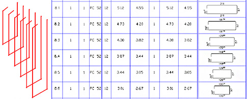


 J-S COURIVAUD: The main saving concerns the drawing time creation which is extremely fast with Advance Steel. In addition, a permanent link exists between the 3D model and all the generated documents using the integrated
  J-C MASBOEUF: We extended the Advance Steel catalogs with steel profiles used for our bridges. We also added new anchors that secure the structure on concrete abutments.
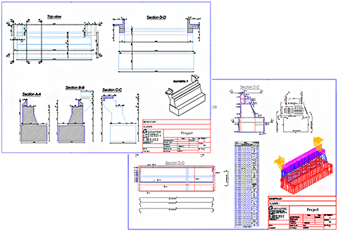
 J-C MASBOEUF: We exported the entire Advance Steel 3D model to the ACIS format and we sent the electronic file to MATHIS, the company in charge of the wooden railing of the bridge. For their part, they completed the 3D model by precisely positioning the overall handrail and other wood laths between the steel posts in inverted V, which required specific and precise cuts at the ends of the wooden elements. Then, this completed model was sent back to us and I could import all the wooden parts in my Advance Steel model to automatically produce overall drawings representing the steel structure, the concrete bridge abutment and all the wooden elements.


 There are different available choices:


 Internationalization is a major theme of version 2012 of


