While searching the forum, I found an intriguing question and I thought I would create a short video to address the issue.
Here is the dilemma, you are working on many projects simultaneously. While jumping from one project to another, you notice that in some of the drawings, your beam orientation is not as you expected.
It would be great if, in the steel structure, you were able to find out the start point of the beam. Did you create the beam from left from right or right from left?
TIP: Advance Steel allows you to view what direction the beam was created.
Open the Advance Steel Tool Palette and select the UCS category, which is the fourth icon in the first column. Within that category select the second icon called “Define coordinate system” in the third row.
After selecting the beam in question, you will find a symbol as seen in Figure1. The symbol shows you that this beam was created from right to left and in Figure 2 the beam was created from left to right.
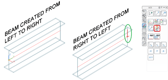
Figure 1
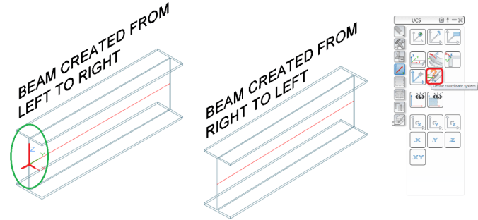
Figure 2


