Take a sneak peek into the brand new BIM Designers Slab Module


GRAITEC BIM Designers Slab Module provides automatic reinforcement design solutions according to international codes and norms for slabs. The module will be introduced to the public for the first time starting with the official release of the 2020 Graitec Advance Suite.

The reinforcement cages for slabs can be designed using individual bars or fabrics that can be selected from large international libraries. They can also be manually customized based on users’ preferences. The module allows designing reinforcement cages made from a mix of fabrics and bars.

Read the full article here

Advertisement

Reinforcement and formwork for complex shapes in Advance Concrete


Reinforcement and formwork for complex shapes in Advance ConcreteThe article describes how we can create reinforcement and formwork drawings for structures with a complex geometry, namely bridge abutment using Advance Concrete. The bridge abutment is a part of infrastructure which is created at the ends of the bridge in order to take the transmitted loads of the bridge superstructure and the supports of the access path to the bridge.

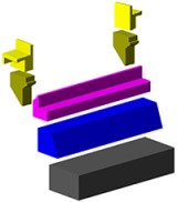
To define the chosen geometry, an ACIS block can be created or the complex geometry can be divided into several blocks having a simple geometry which can be assembled in order to obtain the initial model.

We chose the second method for reasons related to the flexibility of Advance Concrete while modeling volume elements.

How to create any 3D concrete shape

Reinforcement and formwork for complex shapes in Advance Concrete

Advance Concrete provides the creation of any 3D and 2D shapes. The predefined concrete shapes can be chosen from the library or new ones can be created. To add a new concrete shape it is enough to create a closed contour and then save the shape in the concrete library. These new shapes can then be used either in the current drawing or for other projects.

The created concrete elements are defined as beam and column structural elements. These are positioned one in regard to the other, composing the entire concrete ensemble.


How to obtain a 3D reinforcement cage for special concrete shapes

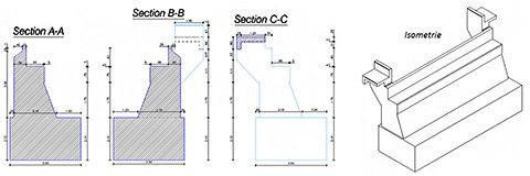
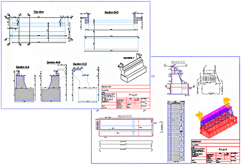
The reinforcement drawing is created by selecting all the concrete elements. In the created reinforcement drawing, sections are added through the specific concrete zones.

Reinforcement and formwork for complex shapes in Advance Concrete

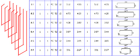
The definition bars are created in one section and then distributed in elevation or top view. Several types of bars (straight, U and L bars) and distributions (linear, variable, multiple and quantitative) are available for use. The most frequent reinforcement bars are polygonal and straight bars and linear and variable distributions. Concrete covers can be set for each leg of the polygonal bar.

Reinforcement and formwork for complex shapes in Advance Concrete

Reinforcement and formwork for complex shapes in Advance ConcreteA reinforcement bar distributed in one view will automatically be available in all views, as long as the 3D power option is activated in the reinforcement drawing.

Reinforcement and formwork for complex shapes in Advance ConcreteIn order to obtain a correct reinforcement cage, the collisions between bars have to be avoided. The bar collisions can be visualized in 2D and 3D representations. They can be easily checked and corrected, at any point.

The bar detailing and reinforcement symbols can be done both manually (they can be customized and saved in the reinforcement symbol library) and automatically.

The bars numbering and lists creation is automatically done. Sub-entity marks are assigned for variable distributions, emphasizing that the variable distribution belongs to a single shape definition bar.

Reinforcement and formwork for complex shapes in Advance Concrete

The drawings are created according to standard STAS 438/1,3 -89. The drawing creation according to other standards is similar.

Formwork details

The formwork drawing is created by adding the desired sections and elevations for structural elements, assigning specific hatches and line weights. The dimensioning of sections is quickly done by adding intersection and level dimensions.

Reinforcement and formwork for complex shapes in Advance Concrete


Layout and Print

The reinforcement and formwork drawings can be placed in any page format. Also the views can be grouped and the title block can be attached according to the chosen format.

Numbering of the reinforcement bars and lists can be done in layout mode. The drawings can be printed one by one or by selecting several from the available print window.

Reinforcement and formwork for complex shapes in Advance Concrete


Test it yourself

We have shown a simple example of a formwork and reinforcement cage created for a complex shape of the structural element. If you want to see the model described above, please download the specific model and drawings from here or, as a pdf file from here.

The example was created in Advance Concrete 2013.

Get your FREE 30-days trial version!

This slideshow requires JavaScript.

Online presentation: ADVANCE Concrete – the high-end concrete detailing software !


Reinforcement Concrete Detailers, Structural Engineers:
Discover the high-end concrete detailing software !
Thursday, May 31st, 2012,
from 9:00 to 9:30 CEST or 17:00 to 17:30 CEST
Register online for this webinar
Advance Concrete: BIM software for structural concrete engineering, detailing and fabrication


Advance Concrete: BIM software for structural concrete engineering, detailing and fabrication


Advance Concrete: BIM software for structural concrete engineering, detailing and fabrication
Advance Concrete® is specifically designed for structural engineers and reinforced concrete detailers who require professional and easy-to-use BIM software that automates the production of drawings, BOMs and NC files. Advance Concrete® drastically increases productivity and drawing quality, while reducing the risk of errors. Perfectly integrated in AutoCAD®, Advance Concrete® accelerates the design phase (single or multi-user mode) by offering an extensive library of structural and reinforcement elements. It generates all construction drawings using intelligent drawing tools automatically controlling dimensions, symbols and drawing layout.Advance Concrete® is part of the GRAITEC structural BIM solution, automating the entire structural design process, from engineering design to detailing and fabrication.

Advance Concrete: BIM software for structural concrete engineering, detailing and fabrication

With Version 2012, significant work was done reworking the software architecture and optimizing performance. This results in a significantly higher ease of use and increased efficiency for users.

Version 2012 also improves rebar detailers efficiency with improved tools for placing rebars and fabrics in identical elements, new options for visual representation and better control of elements as well as new Bill Of Material options.

Advance Concrete 2102 also has much better interoperability thanks to several new features such as DWG export in batch and improved DWF export.

Discover the version 2012 new features on Thursday, May 31st, 2012

Register online for this webinar

Advance Concrete Dynamic Reinforcement


Creation of the reinforcement drawing is an important step in designing reinforced concrete buildings, which usually involves a lot of time, patience, skills and responsibility, as the created drawings should comply with specific standards.
Advance Concrete has a new reinforcement solution, easy to use in projects, so that the time spent for reinforcement drawing creation is considerably reduced.

1. Predefined dynamic reinforcement solutionsAdvance Concrete: Dynamic reinforcement

  • Cantilever beams
  • Columns (stirrups and pin bars)
  • Door and window openings
  • Wall between two columns
  • Plain wall between walls

2. Flexibility in defining new dynamic reinforcement solutions
Advance Concrete provides:

  • A user friendly environment for reinforcement solution design
  • Various tools for the creation of all reinforcement elements necessary for the reinforcement cage
  • A wizard for saving the dynamic reinforcement solution

3. Easy to use

  • Automatic creation of a drawing from a set of structural elements. The drawing contains predefined views
  • Adding reinforcement elements using the Advance Concrete tools
  • Saving the reinforcement solution in an interactive mode

4. Reusing the reinforcement solutions
All reinforcements put in place using the “Dynamic Reinforcement” automatically adapt to formwork contours and can be taken into account in reinforcement drawing creation and lists.

5. 3D ViewAdvance Concrete: Dynamic reinforcement
Based on the reinforcement representation in the views of the reinforcement drawing, Advance Concrete recreates the cage and displays it in 3D. It also detects collisions.

Benefits

  • The dynamic reinforcement solutions can be easily used in projects, so that the time spent for reinforcement drawings creation is considerably reduced. Common tasks, frequently encountered during the project development are simplified and reduced to simple parameter value input.
  • Once defined and saved, the dynamic reinforcement solutions can be applied in other projects; this minimizes the risk of errors and guarantees compliance with design rules and standards.
  • The drawings are kept up-to-date when projects are modified, and the risk of errors is considerably reduced.

Read full article here


Advance Concrete – Reinforcing load bearing walls


Advance Concrete provides advanced reinforcement solutions, useful in designing reinforced concrete buildings so that the time spent for creation of the reinforcement drawings is considerably reduced.

Nowadays, many private or office buildings are built using load bearing walls as main supporting elements. In a vertical plane, the load bearing walls have a large capacity of processing gravitational loads, which recommends them for buildings with several levels, in seismic areas. On the other hand, in a perpendicular direction on the wall plane, the load bearing walls provide small resistance to horizontal forces and usually are supported by perpendicular walls or similar structures.

In this article you will read about:

  • Fast creation of all reinforcement elements
  • Automatic creation of a drawing
  • Adding reinforcement elements
  • Defining formulas when saving the solution

Click here to read full article