by Stevens Chemise Product Line Manager at GRAITEC
Abstract
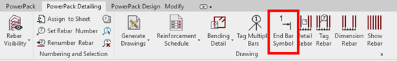
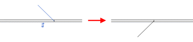
PowerPack for Revit propose an End Bar Symbol command, available on the Detailing ribbon. It allows for a quick definition on 2D views a special symbol showing location of ends of straight bars
PowerPack for Revit propose an End Bar Symbol command, which is useful especially for cases, when rebars overlap on the view to clarify reinforcement drawings.,
The End Bar Symbol command supports two usage scenarios:
called with existing rebar selection – symbols are defined automatically at both ends of selected bars,
called without any selection – a symbol it is defined at the end which is closer to the indicated point on the bar.
The type of bar end symbol depends on the family used (Detail items category). The default family and type are selected in the Reinforcement Configuration window.
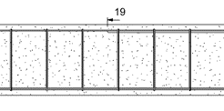
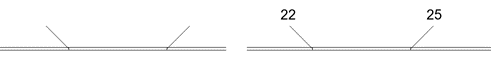
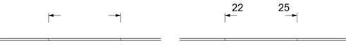
The family supplied with the program (Graitec EndBarSymbol) contains two types of symbols:
tick (with or without bar mark annotation)
tag (with or without bar mark annotation)
This family also allows for easy configuration of the size of the components as well as easy flipping
Often in the steel structure detailing projects, we have the situation when the same type of connection is available, but with a different configuration, even if we talk about one parameter. Even if the configuration is different, the detailer might need to change one or more common properties of those connections.
Today, in Advance Steel this is possible with the functionalities around the “Group joints” feature, but with certain limitations. The limitations are related to the fact that the joints must be the same type and have identical configurations (master and slave behavior)
2. Joint Multi-Edit
The Joint Multi-Edit available with GRAITEC PowerPack for Advance Steel is allowing the user to change parameters in two or more joints from the same category but with a different configuration. The joints do not need to be grouped or have any master and slave behavior.
2.1. Criteria:
The criteria to enable this feature is to select 2 or more joints with are part of the same category: Base plate, Corner Base Plate, Gusset plate at 1, 2, 3 diagonals, Create Stiffeners, etc.
2.2. Example:
Following, to understand better how this feature can be used, an example with the Corner Base Plate joint will be explained.
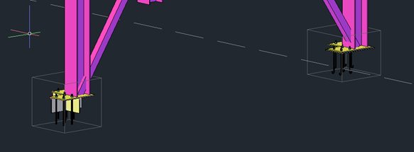
Two columns with the Corner Base Plate joint are created but, as it can be seen, the configuration is different:
Different anchors
Different base plates dimensions
Shear lug enabled or not
Leveling plate enabled or not
Figure 1: Lateral view
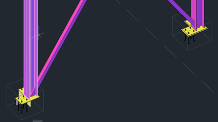
Figure 2: Top view
To access the command Joint Multi-Edit:
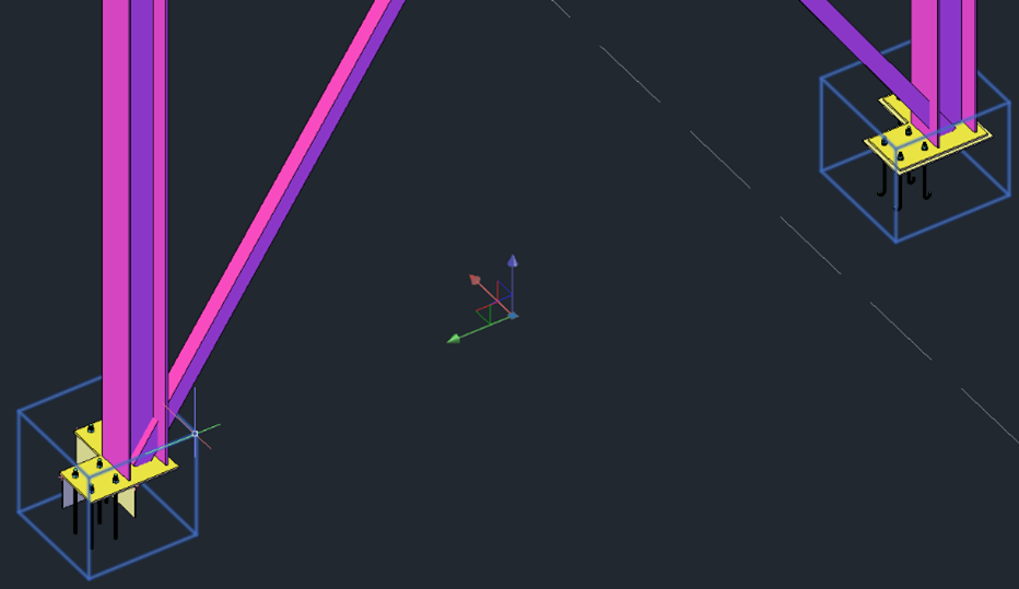
Select both joint boxes
Figure 3: Selection of joint boxes
Right-click to open the active menu and search the “GRAITEC PowerPack Joint Multi-Edit” command
Figure 4: Right-click menu – command Joint Multi-Edit
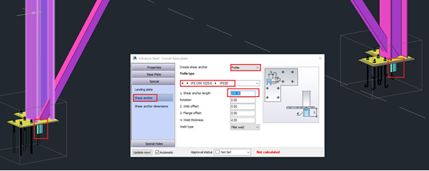
When the command is selected, the dialog of the joint will be displayed.
Note: The configuration of the last joint selected is the one displayed in the dialog when this is opened with the Joint Multi-Edit command.
Figure 5: Configuration of the last selected joint
Now, when any parameter is changed, the change will be propagated to all selected joints for which the multi-edit command was activated.
Figure 6: Changes’ propagation – Shear lug type
Figure 7: Changes’ propagation – Base plate dimension
The command is working with any joint category from Advance Steel as well as on any joint from the PowerPack.
With Graitec PowerPack for Revit, a specific functionality has been introduced for assigning reinforcement to a layer (for example Top or Bottom) for easy and quick filtering of the reinforcement.
The layer might refer to a geometrical location of reinforcement but also to another purpose, such as its function.
The information about the assigned layer is stored using shared parameters: G.Rebar Location for Structural Reinforcement and G.Fabric Location for Structural Fabric Reinforcement.
The assignment is done automatically and manually. The automatic method is applied during reinforcement generation using calculation modules or reinforcement generators in PowerPack. For example, the top bars in the foundation have an automatically assigned value T (a default name for a top reinforcement). Automatic assignment is made to the selected rebars, for example in the case of a foundation to the lower and upper bars in the pad.
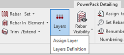
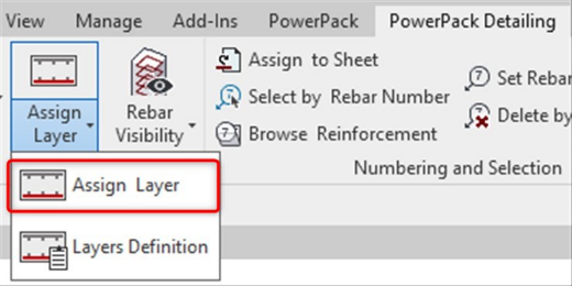
The manual assignment is done for selected reinforcement using the Assign Layers command, which is available in the PowerPack Detailing ribbon.
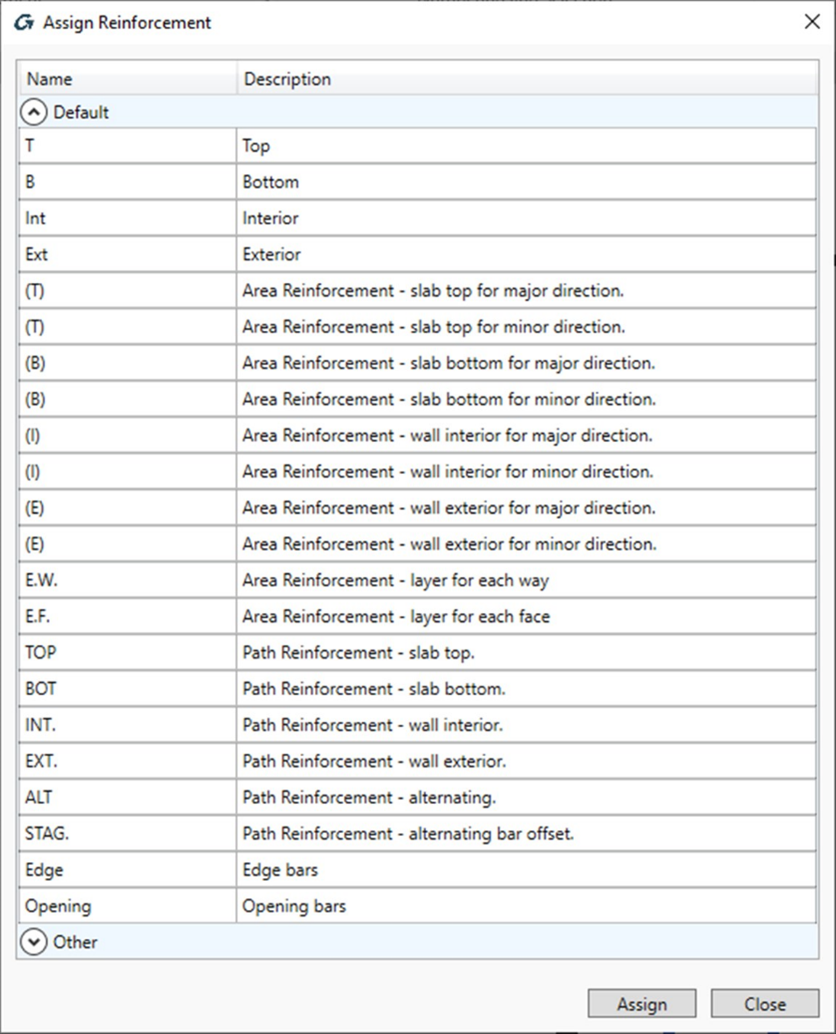
The Assign Layers command opens a special dialog with the list of default/predefined layers.
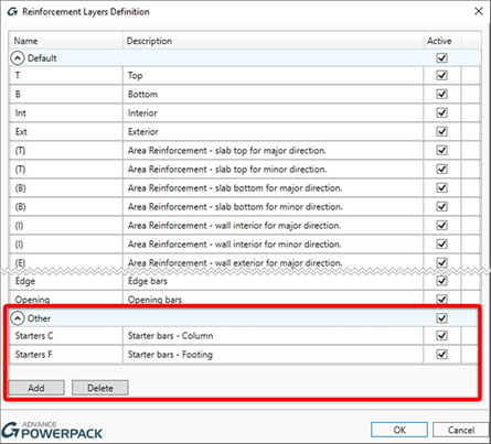
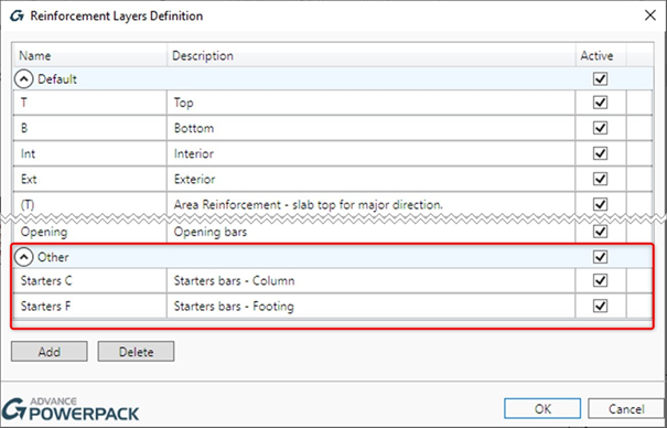
The content of the list is based on the configuration from the Reinforcement Layers Definition window, opened by the Layers Definition command. The user can modify names for default layers, use the Active option to limit the list of layers that can be available during the assignment and add new positions/layers to the Other group.
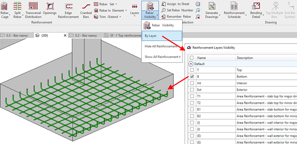
The value of the layer parameter is mainly used in the new options of the tools for controlling the reinforcement visibility
In fact, in the Rebar Visibility functionality, there is a group of options for selecting by layers.
When the Top or Bottom option is selected, then an additional filtering for reinforcement is activated, respectively by the top and interior or the bottom and exterior layers. When the Selected option is active then the selection of layers for displaying is done through the dialog opened by the Select Layers button .
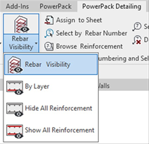
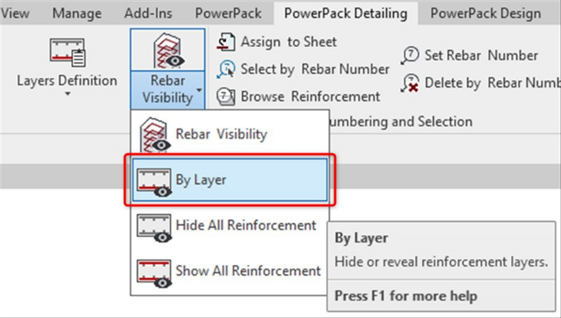
In addition, three new commands are available under the drop-down list under the Rebar Visibility: By layer, Hide All Reinforcement and Show All reinforcement.
Hide All Reinforcement and Show All Reinforcement allow you to quickly turn off or on the visibility of the entire reinforcement in a given view. By Layer allow you to quickly select the reinforcement to be displayed by using the Layer property.
This is particularly useful when generating drawings with separate views, e.g. for bottom/ top reinforcement for slabs or foundations.
Graitec PowerPack propose a specific command for assigning reinforcement to a layer (for example Top or Bottom) for easy and quick filtering of the reinforcement.
The layer might refer to a geometrical location of reinforcement but also to another purpose, such as its function.
The information about the assigned layer is stored using shared parameters: G.Rebar Location for Structural Reinforcement and G.Fabric Location for Structural Fabric Reinforcement.
The assignment is done automatically and manually. The automatic method is applied during reinforcement generation using calculation modules or reinforcement generators in PowerPack. For example, the top bars in the foundation have an automatically assigned value T (a default name for a top reinforcement). This automatic assignment is made to the selected rebars, for example in the case of a foundation to the lower and upper bars in the pad.
The manual assignment is done for selected reinforcement using the Assign Layers command, which is available in the PowerPack Detailing ribbon.
The Assign Layers command opens a special dialog with the list of default/predefined layers.
The content of the list is based on the configuration from the Reinforcement Layers Definition window, opened by the Layers Definition command. The user can modify names for default layers, use the Active option to limit the list of layers that can be available during the assignment and add new positions/layers to the Other group.
The value of the layer parameter is mainly used in the new options of the tools for controlling the reinforcement visibility. Indeed, to the Rebar Visibility functionality, a new group of options for selecting by layers is added.
When the Top or Bottom option is selected, then an additional filtering for reinforcement is activated, respectively by the top and interior or the bottom and exterior layers. When the Selected option is active then the selection of layers for displaying is done through the dialog opened by the Select Layers button.
In addition, three commands are available under the drop-down list under the Rebar Visibility: By layer, Hide All Reinforcement and Show All reinforcement.
Hide All Reinforcement and Show All Reinforcement allow you to quickly turn off or on the visibility of the entire reinforcement in a given view. By Layer allow you to quickly select the reinforcement to be displayed by using the Layer property.
This is particularly useful when generating drawings with separate views, e.g. for bottom/ top reinforcement for slabs or foundations.
Article by Stevens Chemise / BIM Industry Manager / GRAITEC France
Revit propose a process to create reinforcement for most structural members, based mainly on two steps: first place the rebar shape in an appropriate section view and then distribute it in an elevation or the opposite, place the rebar shape in an elevation and then distribute it in a section (for longitudinal bars for example).
This manual and repetitive process therefore involve multiple manipulations and frequent switching between Revit views.
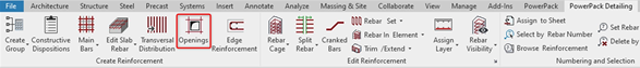
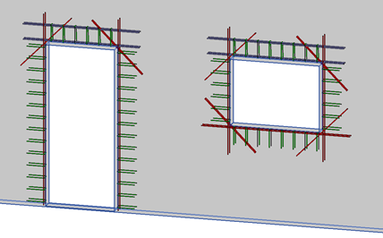
Whether for slabs or walls, the reinforcement of any kinds of openings is a recurring operation during projects. This technical aspect is addressed by one of the functions of the Graitec PowerPack, Reinforcement Openings.
This Openings command is used to quickly generate constructive reinforcement around openings. It is available on the PowerPack Detailing ribbon.
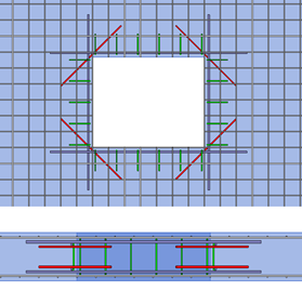
The command enables the generation of reinforcement around openings on slabs and walls. It allows as well rebars generation for multiple separate openings at once. For a selected opening , it opens the configuration window with parameters related to concrete cover and tabs for different reinforcement bar types.
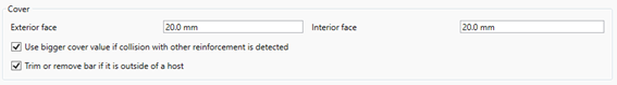
The Cover section allows the manual control of the cover, the automatic cutting of bars in case of holes close to the edge and the option to automatically adjust the cover to the existing reinforcement, to keep the correct 3D arrangement of bars.
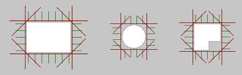
The remaining parameters are available on independent tabs separately for four optional reinforcement types: Main bars (longitudinal bars along edges), Diagonal bars (bars that are perpendicular to bisectors of corners), Edge bars (transverse bars along edges) and Lintel bars (longitudinal and transversal bars above openings on walls). Thanks to the wide range of settings, many different bar configurations are possible.
This new version 2022 has added a special option of opening rebar for door by the possibility to add or not the bottom diagonal rebar.
In the case of non-rectangular shapes of openings, the reinforcement is generated on its rectangular external perimeter
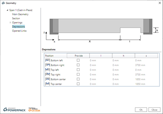
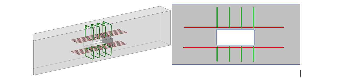
For beams, users may have to deal with several situations with openings such as placed within the beam, a depression … For all those situation, Graitec PowerPack provide some dedicated tools.
Firstly, the command Main bars or Constructive Dispositions can generate a 3D rebar cage on beam, even those one with custom shape including openings and depressions.
Then, it is also possible to add reinforcement around an opening in a beam with a dedicated command. This opening could be created by the native command By face.
With the new release of the Powerpack for Revit 2022 we are launching the new rebar drawings generator.
In this post I am intending to explain the concept behind the tool, assumptions that were made in order to obtain the best results and at the end I will add some tips&tricks.
As you know, we already had a view generator in the Powerpack. There were 2 issues that were making the mechanism basically unusable:
The mechanism used an external Revit file that contained the drawing configurations. Therefore, there was no initial link between the user’s Revit project and our drawing template. Of course, our template could have been customized but it would had presumed some time.
In order to work properly, the rebar cage needed to be generated with the Powerpack so that rebars could have roles. After the generation, the mechanism knew the roles of the bars and knew what to do with them.
We decided to stray from this approach and we established the main pillars the mechanism will be based on:
The mechanism will be totally based on the user’s Revit Template.
It will use the active project’s view templates, detail view types and rebar schedules. It will read the Multi-Rebar Annotation, Tags and Title blocks families.
The rebar cage inside the element can be manually modelled or generated by the Powerpack.
The section of the elements will not be an issue. The mechanism will work the same for cast-in-place or pre-cast elements.
We will implement the mechanism is such a way that it will take account of the user’s browser organization sorting rules by inserting Revit’s View parameters also.
We will be able to generate wall drawings also.
In a few words, this is how the mechanism works:
Using the drawing manager, the user will make his own drawing configurations for each category of elements (Beams, Columns, Walls, Foundations)
The user will run the command and he will select the elements.
After the selection is made, the grouping algorithms will decide if the elements can be treated as a group or not.
The configuration dialog will appear, and the user is able to change the configurations.
The drawing managerSelection of elementsCreate views dialog
Using the user’s Revit Template
This part of the implementation was easy-to-do. However, during the development we ran into the issue of multiple projects. We decided to not put the user to make the drawings configurations each time he starts a new project (Assuming that users have the same revit template).
We decided to create an .xml file that will contain all the configurations made by the user. This way, the settings will always be there when the user starts a new project. Of course, modifying the Revit template to a completely different one means that you should do the configuration again.
The .xml file is placed here: C:\Users\<User>\AppData\Local\Graitec\Advance Design modules\2022\Templates\Revit\DrawingConfigs
Furthermore, with this approach, the .xml file can be shared across the office. This way only one person needs to make the configurations.
Supported elements and Rebar cages
The mechanism will work the same for any Revit Family. We are not using any mapping mechanism. Any Loadable family will be supported. Model-In-Place elements are not supported.
We established that we needed to perform the drawings regardless of the method the rebar cage was obtained (by hand or generated by the Powerpack). In order to achieve this, we needed to use the Style of the rebar shape family.
Quick recap: The style of the shape can be Standard or Stirrup/Tie. There are no geometrical differences between these two, any rebar shape can be set as either of them. The difference comes from Revit’s rebar constraints mechanism. When placing a stirrup/tie bar, it will search for the nearest host rebar cover. Standard bars will additionally search for the stirrup bars handles. Basically, the Stirrup knows that it needs to tie Standard bars. This is especially helpful when modelling rebars by hand.
Thus, we are using the style of the rebar as an input parameter in order to know on which bars we are placing Multi-Rebar Annotation or for which bars we are generating bending details.
This is probably the most important point in order to achieve proper drawings.
Example:
Rebar shape styles
Drawing manager dialog
We needed to let the user configure his drawings according to his Revit template and requirements. The dialog will manage the Annotations, Bending details (General page) and drawing configurations (Element category pages).
In the following I will explain all the options inside the dialog.
General page
Generate views only by default configuration – Checking this option will bypass the Create views dialog. The drawings will be generated according to the check at the left of the configuration in the left panel. It was intended to speed up the process.
Name – The name of the annotation configuration. It will be further used in the drawing configuration
Rebars – The rebars that the user wants to place Multi-Rebar Annotations on.
Rebar Presentation – How the users wants to show the rebars in the generated view. Examples: Central bar, three in the middle…
Multi-Rebar Annotation – The family that the user wants to use for this drawing. The list will contain all the MRA inside the project
Group MRA – If the elements has multiple distribution of the same rebar number you can group the MRA in order to obtain a single distribution symbol. Example: For a beam with stirrups distributed on 3 zones you can obtain 3 MRA or only 1 MRA.
Multiple Tag Family – On rebars that are not distributed, we are placing rebar tags using our own tag multiple bar command. The user needs to set what tag family he wants to use.
Bending detail family – What family the user wants for the generated bending details
Drawing configurations:
View type – what kind of drawing the users wants his configuration to contain. He can choose from a list that is different for each element category.
Revit view type – We used detail views for the drawings. The user can choose what detail type he wants for his drawings. We considered that this option might be used also for the browser organization. The list will contain all the detail view types in the model.
View Template – What view template the user wants to apply to the view. The list will contain all the view templates in the model.
View scale – At which scale the user wants to generate the drawing. If the view template has the scale included, the value in the dialog will be ignored.
Length ratio: Percentage of the length/height of the element at which the section/plan view/node detail will be generated.
Annotation – the annotation configuration that the user wants to use in the drawing. The list will contain the configurations from the General page
Bending detail – the bending detail configuration the user wants to apply to the view. The list will contain the configurations from the General page.
Rebar schedule category – what type of rebar schedule do you want to generate for the select element (Structural Rebar, Fabrics etc.)
Rebar schedule type – a template that will be used for the newly generated rebar schedules. The list will contain all the schedules inside the model according to the selected category.
Titleblock - A list of all the titleblocks in the model
Revit View parameters and Browser organization
Browser Organization
Advanced Revit projects are using a different browser organization rule. They are doing this with a combination of Revit View Parameters. We decided that the drawings should not be randomly generated and should take advantage of the user’s browser organization.
In order to do this, we needed to read the project’s view parameters and include them in our drawing configurations.
Add Revit View Parameters
First you need to add them into the drawing manager by clicking on the “Manage” button. Some parameters might be included in the view templates definition, so you do not need to include all of them. After adding them in the drawing manager, for each configuration, at the end of the table, new columns will be added.
Revit View parameters added to the configuration table
If you want all your drawings to have the same value for a parameter, you should insert the value into the drawing manager. However, if your values differ for each element, you should insert them into the Create Views dialog.
Grouping algorithms
Users have different ways of modelling in Revit so we needed to develop some connection algorithms that will allow us to group elements. Each element category needed to have its own grouping algorithms. Also, the grouping was made accordingly to the desired drawings.
We also took account of the design groups made in the Powerpack. Thus, if there are Multi-Span Beams or groups of Walls the user will need to select only one element inside the group.
Beams
For individual beams to be treated as a group they need to fulfill these two conditions:
They need to share a node.
Connected node in order to treat beams as a group
Their axis need to be coplanar.
Different examples for beam groups.
Grouping will allow the user to generate a full-beam elevation of elevation per each span. Sections will be placed for each span.
Columns
There are users that model columns individually for each level or who model them throughout the full height of the building. We needed to be able to obtain full column elevation. We also support slanted columns.
To be treated as a group, columns need to fulfill these conditions:
They need to be concurrent.
They need to share the same X and Y global coordinates
Column Groups
Walls
Structural walls are usually complicated drawings. They contain a lot rebars and usually they need multiple types of drawings (plan views, node details, sections, elevations and so on)
Wall groups are also different from the other element categories because they need to be grouped on 2 different planes. First they need to be grouped on the horizontal plane in order to obtain the plan view and then they need to be grouped on the Z direction in order to obtain the full elevation.
The discussion regarding the manner of modeling walls is the same from the column. They can be modelled individually or through the full height of the building, so we needed to address this issue.
In order to treat them as a group they need to fulfill these conditions:
For proper plan views:
They need to share the same Base Constraint, Base Offset, Top Constraint and Top Offset
They need to share an edge
For proper elevation:
They need to be concurrent
They need to share an edge
Wall groups
Final results:
Full beam elevation with sectionsWall drawings
Final Tips&Tricks
Pay attention to rebar styles (Standard and Stirrup/Tie)
I recommend making dedicated View Templates to each element category. This way you can automatically hide unwanted rebars or sections
You can use multiple bending details tags
You can use this tool also for the initial views the user needs to have in order to place the rebars. Generating drawings without multi-rebar annotations and bending details will be instantly done. You can use this in your advantage.
GRAITEC, an international BIM and CAD software developer for AEC, and Autodesk® Platinum Partner in US and across Europe, is delighted to announce the launch of Advance PowerPack for Autodesk® Revit® 2018, compatible with both Autodesk® Revit® 2017 and 2018.
GRAITEC is constantly improving its products to provide first-rate productivity tools for its valued customers, and the recent launch of the PowerPack for Autodesk® Revit® 2018 is no exception to this rule, as it delivers a set of new powerful tools, as well as several improvements to the existing toolset to help boost productivity in Revit®.
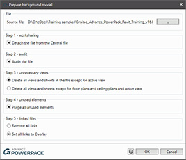
In version 2018 of the PowerPack, cleaning up your architectural background files before linking them to structural or MEP models has never been easier with the new Prepare Background Model command in the Files group.
The Link Background Model function is another powerful new tool, that links the architectural background file in the MEP or Structural model, allows users to transfer project standards from the linked file, enables copying scope boxes from the background file and make the link room-bounding.
The third new addition to the Files group is the Create Views command, which rapidly and efficiently creates views based on view templates, allowing multiple levels/view templates selection.
Prepare Background Model
Link Background Model
Create Views
One of the major changes in this version is the migration of the Reinforcement panel from PowerPack for Revit ribbon to the Reinforced Concrete BIM Designers application, as a result of users demand for a more compact reinforcement package, that includes calculation, cage generation, drawings, reports and detailing, from a single set of tools.
Another ribbon-related change involves the addition of the new category of structural modeling tools, used for verifying and correcting the analytical model of Revit projects and obtaining correct FEM results after exporting them into Advance Design.
The new tools in the set are used for resetting manual adjustments of analytical models (Reset Analytical Models), automatically trimming/extending the extremities of close objects (Trim or Extend), stretching the closest extremities of selected elements to a reference point (Stretch to Node), or indicating elements that seem to be connected but from a calculation point of view are not (Detect Errors).
Version 2018 also comes with two new modeling tools: Join & Unjoin Geometry, which automatically joins, unjoins or switches the join order of selected element categories, and Pipe insulation, which automatically assigns insulation to the systems based on parameters such as the outer or inner diameter, or assigns a specific value.
Other important improvements and news include the new interface in Russian, as well as the custom installation packages, which allow individual installation of certain PowerPack functionalities, such as Family manager, Link to Excel and Watermark Manager.
Joseph Pais, GRAITEC Products Director adds: “We are constantly encouraged by the excellent feedback and productivity gains reported by Revit PowerPack users around the globe.
The latest enhancements and new functionality that Revit PowerPack 2018 delivers stem from the proactive and rapidly growing community of users. Our vision match with our customers will help make Graitec Revit PowerPack the most powerful set of productivity tools available for Revit users in keeping with our strategy to become a global leading BIM provider and combining Autodesk and GRAITEC technologies to deliver real benefits to customers“.
With BIM adoption in full swing in the UK and America and emerging mandates across Europe gearing towards Building Information Modelling, we are pleased to announce that our Graitec Advance PowerPack for Revit review on the Engineering.com website has been voted at 4th place in the top 10 Revit content 2016 by Revit News.
As an established international software developer of a variety of BIM tools, Construction software and Structural Design Analysis solutions, the Graitec Advance PowerPack for Revit has been made available with support in multiple languages and has been designed to deliver Revit users with powerful tools that enhance productivity for many day to day design and modelling tasks for example a Revit to Excel Link, Batch Export to DWG facility, Revit Family Manager, Renaming and numbering tool and so much more.
Achieving independent recognition for our software is very welcoming indeed as it shows we are continuing to provide productive solutions that meet our clients daily needs.
The Advance PowerPack for Revit is available free of charge for Graitec’s subscribers or can be purchased if required.
AUGIWorld is the official magazine of Autodesk User Group International (AUGI), distributed on a monthly basis to all AUGI members around the world.
In the June 2016 edition, Gareth Spencer, BIM Consultant working for GRAITEC and certified professional in Revit Architecture and Structure, presents the advantages of using GRAITEC Advance PowerPack for Revit for enhancing concrete detailing. Gareth explains the necessity of modeling reinforcement in the 3D Revit model, and introduces the GRAITEC Advance PowerPack for Revit as a versatile add-on for Revit, which can help users work more efficiently.
Gareth presents some of the most useful tools in PowerPack, such as:
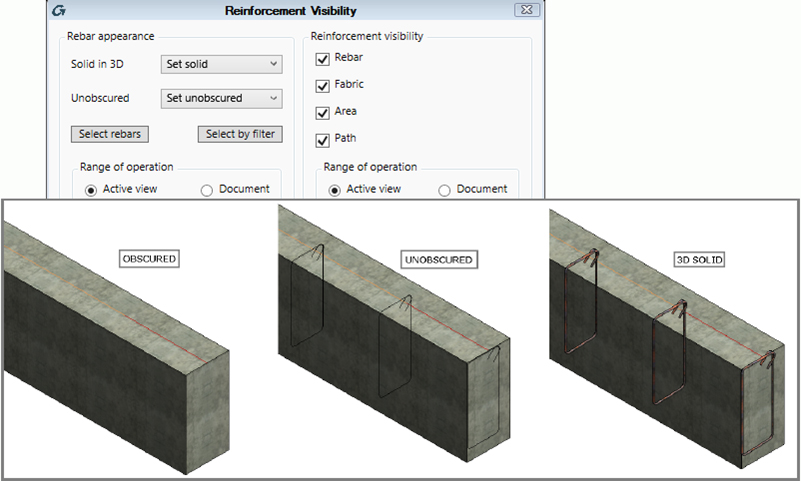
Rebar Visibility, used for changing the view’s visibility state, so as to show rebar unobscured and/or as solids in 3D views, or for hiding certain elements;
Copy Rebar, allowing users to select element rebar, and then copy it to an identical or similar element with no reinforcement assigned;
Transversal Distribution, which automatically generates transversal rebar sets with multiple spacing for linear elements.
Trim/Extend, used for adjusting the created reinforcement to the shape and particularities of the host element, in a quick and intelligent manner.
These useful new tools are complemented by several commands and functionalities for increasing productivity while working in Autodesk Revit:
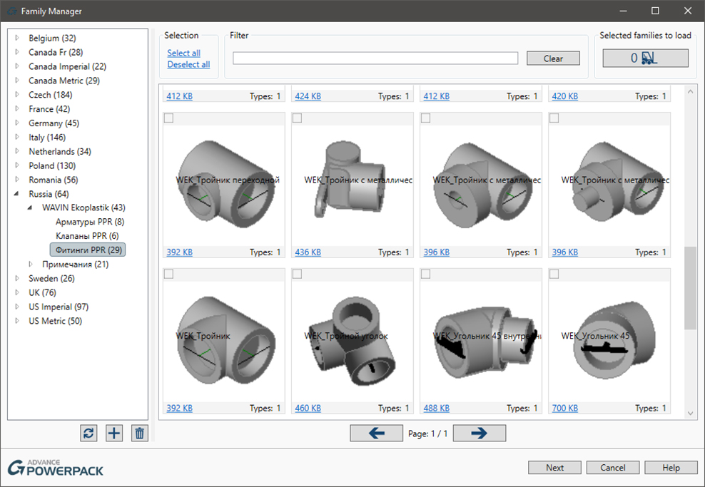
Family Manager, used for managing Revit families (by searching, selecting or filtering family lists to select the desired families to be imported in a project), either on a local computer, or in a company network;
Family Exporter, allowing users to select and export all families at once, or select desired families from the list;
Auto Section Box, which automatically creates a 3D view of the selected elements, and even duplicates it;
Dimension Annotations, a set of tools for automatic generation of dimension lines for overall dimensions, grids, external geometry, structural, and openings.
• Explode drawings from the Document Manager to .dwg format
• Instantly transforms Advance Steel dimensions into AutoCAD dimensions
• Dimensions retain their intelligence enabling editing in AutoCAD
• Select individual or multiple drawings
Updated Glass Panels
• Insert multiple glass panels at once
• Use any profile shape or material
• Easily define single and multi-layered glass
• Create a reusable library for windows, railings and structural glass
Create corrugated beams with this new feature
• Easily create a beam with an undulated web
• Use either a beam from the catalogue or user defined
• Control all dimensions that define the beam
GRAITEC, international BIM and CAD software developer for AEC and all round structural industry specialist, is delighted to deliver even more tools in the latest version of the Advance PowerPack for Autodesk® Advance Steel 2016.
The new version of GRAITEC’s Advance PowerPack for Autodesk® Advance Steel includes a wealth of functionality and productivity tools to ensure customers achieve a true competitive advantage when using Autodesk® Advance Steel 2016.
The latest version, which is in addition to all previous tools, introduces several new connections, tools for setting out complex helical stair stringers, links with cloud services and a suite of commands for transforming Advance Steel drawings into AutoCAD compatible versions, whilst retaining intelligent scaled and editable dimensions.
GRAITEC customers receive the PowerPack for Advance Steel as a complimentary addition to their Autodesk® Advance Steel subscription and service contract, or it is available to purchase separately from GRAITEC or one of our global partners.
Carl Spalding, GRAITEC Product Strategy Director comments: “Initially the PowerPack was a way for us to deliver additional tools and unique value to customers. The rapid adoption by users around the world and the incredibly positive response has been very impressive. Each version introduces more tools, more automation, and more functionality enabling customers to boost their output and improve quality. It is encouraging to see how the tools we provide can make such a massive difference and it is no wonder the PowerPack is quickly becoming the must-have tool of a busy and competitive design office.“
Create and amend Castellated and Cellular Beams
• Increase beam depth and strength with no additional material
• Reduce weight and space without compromising strength
• Ultimate flexibility when creating castellated or cellular beams
• Create from catalogues, or user defined for full modification
• Add, adjust and control cellular beams
GRAITEC announced the release of Advance PowerPack 2016, its complementary extension to Autodesk® Advance Steel 2016.
In line with the recent release of Autodesk® Advance Steel 2016, GRAITEC releases Advance PowerPack 2016 for Autodesk® Advance Steel 2016, with many new tools, utilities and functions, plus updates to existing features. This new version introduces a wealth of localized manufacturer profiles and more predefined default settings, whilst new tools for creating splines of complex helical stair stringers expands the toolset for high-end stair manufacturers, and tools for automatic creation of floor coverings, based on standard grating sizes addresses more needs of its plant users.
The 2016 version also introduces cloud connectivity and crucially integrates bidirectional links with Advance Workshop, GRAITEC’s newly launched Steel Fabrication MIS solution, enabling Advance Steel users to retrieve and graphically display colour-coded production statuses in their models.
GRAITEC Autodesk® Advance Steel subscription customers will benefit from complimentary access to the Advance PowerPack 2016 as part of their subscription contract, taken or renewed with GRAITEC, whilst others are able to purchase the Advance PowerPack for Advance Steel directly from GRAITEC or from one of their extensive partners worldwide. The Advance PowerPack 2016 for Advance Steel is available to download with a five day free trial, directly from the GRAITEC website.
This step by step guide will show you how to download, install & activate GRAITEC PowerPack Advance Steel 2016.
GRAITEC Advance PowerPack is a powerful time-saving extension to Autodesk Advance Steel that boosts everyday capability, productivity and efficiency.
This new version, GRAITEC Advance PowerPack 2015.1, extends the functionality of existing content and introduces industry-dedicated performance tools such as:
Curved Element Cut
Accurately cut any a straight or folded plate, section or tube to fit the profile of a curved tube
Glass Panel Utility
Define and drawglass panels, windows and facades (c/w material list template)
Platform Cover Creator
Automatically creates a grating or plate platform based on the selected supporting members
GRAITEC, an international BIM and CAD software developer for AEC, and all round structural industry specialist, is excited to announce the new version of their complementary productivity tools, GRAITEC Advance PowerPack for Autodesk® Advance Steel 2015.1.
The GRAITEC Advance PowerPack is a powerful extension to Autodesk® Advance Steel, created to boost the user’s capability, productivity and efficiency whilst introducing a unique set of tools, templates and connections designed to enhance and speed up project delivery. This new version extends the functionality of existing content and introduces industry-dedicated performance tools such as:
Glass module: for managing and inserting glass windows and panels
Curved element cut: for complex contouring of profiles to curved tubes
Platform cover: Instant creation of grating and plate for platform covers
GRAITEC’s Autodesk® Advance Steel customers have exclusive access to the GRAITEC Advance PowerPack 2015.1 as part of their maintenance contract. The latest version is available to download now from the customer Advantages portal or from the GRAITEC PowerPack website.
Carl Spalding, GRAITEC Product Strategy Director comments: “GRAITEC strives to deliver an unrivalled user experience and our PowerPack for Autodesk® Advance Steel is just one of the many tools we provide to our customers as part of that commitment. We have almost three decades of experience delivering professional technology for the steel industry, and we have always been able to react quickly to deliver functionality that helps our customer’s become more productive and competitive. Being able to improve performance, quality and efficiency for all our customers globally, through initiatives like the PowerPack, is a great way for GRAITEC to deliver benefits that reflect the specific needs of our customers.“
Canada – The GRAITEC Canada team is pleased to announce that they will be participating in the Construct Canada exhibition in Toronto, on 3-5 December 2014 in partnership with SolidCAD Solution, an Autodesk Platinum Partner.
The 26th Annual Construct Canada will be held concurrently with PM Expo, HomeBuilder & Renovator Expo and Concrete Canada on December 3-5, 2014 at the Metro Toronto Convention Centre, South Building.
Moreover, Graitec will be presenting its new solution; PowerPack for Advance Steel, a series of plug-ins, tools, new features for Advance Steel.
Come see us, to be part of the GRAITEC BIM Revolution.
GRAITEC Canada at SolidCAD Solution booth Booth#1117
Construct Canada – Toronto, Canada 3-5 December 2014