Advance Design Steel Connection – part II Advance Design                            


by Adriana Gherlan
Steel PowerPack Manager

Abstract

This article is the second one in a series of 3. In this series, you will find basic information about Advance Design Steel Connection: what it is, how it can be used, and which are the main features of the module.

This second article will explain how to use the Advance Design Steel Connection module in the Advance Design environment.

Keywords: #steeldesign #connections #advancedesign

1. Advance Design environment

Advance Design allows the creation of different types of connections between the steel profiles. Connections can be created in the modeling step and the analysis step as well. Advance Design also performs the connections errors verification. The verification function, available anytime during the modeling and also at the creation of the analysis model, displays in the command line the connections modeling errors and warnings (if any).

2. Create connections in Advance Design

The creation of the connections between steel members is very easy. Once the steel structure is defined the connections can be added.

The connection types are available in the contextual menu at the right click based on selection or the ribbon.

Connections – Contextual menu

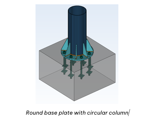
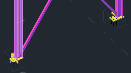
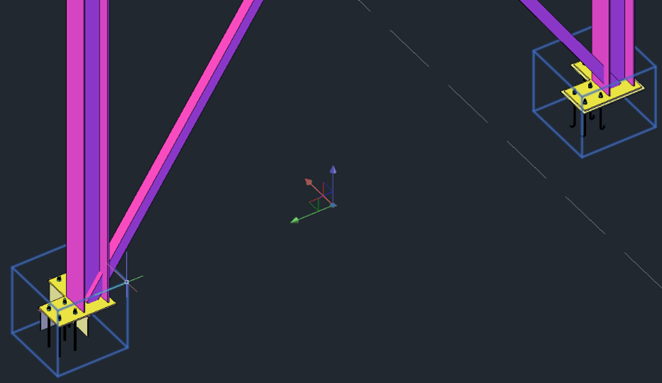
Adding connections using the contextual menu, is done by selection. For example, if we want to add the base plate connection for all the columns, just select all the columns and choose the base plate from the connection list. This will instantly add all the base plate connections for all selected columns.

For an APEX connection selecte all the rafters and from contextual menu choose the corresponding connection: Connections -> Create on selection -> Fixed Connections -> Beam-Beam fixed connection

Therefore, in less than a minute the connections are created within the Advance Design model.

3. Group Connections in Advance Design

The option for Group connection is created to boost productivity and optimize the workflow.

To group the connections, select the connections you want to have in one group and do a right-click to access the contextual menu. From there choose the Connections -> Group.

More than that, the connections which are grouped will be renumbered to see from which group they belong.

4. Connection Design

Once the calculation is done, in the Design tab of the Advance Design Pilot, we can find the Connections. As you will notice, only one type of connection is available for design.

Before opening one of the connections and starting to design it, you must not forget to check the different options available for the Design Modules, including the Advance Design Steel Connection:

Based on the selected options, different loads and envelopes will be transferred to the steel modules:

  •  Always transfer user-defined envelopes to Design Modules for steel connections elements

This option should be checked in case you have specific envelopes defined by you and you need them in the steel connection design

  • Export loads to design modules – Load cases and corresponding efforts diagrams/torsors

This option will export just the load cases and the corresponding efforts per load case.

  • Export loads to design modules – Load cases and corresponding efforts diagrams/torsors with the list of combinations

Besides the load cases and efforts, this option will export also the combinations.

  • Export loads to design modules – Load cases and corresponding efforts diagrams/torsors with the list of combinations + combination values of efforts diagrams/torsors

This last option will export also the combination values of the efforts.

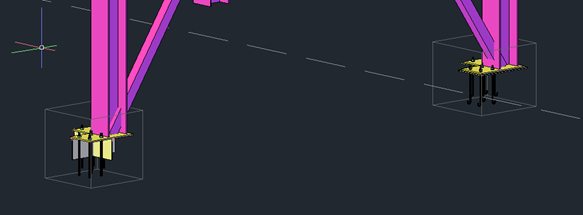
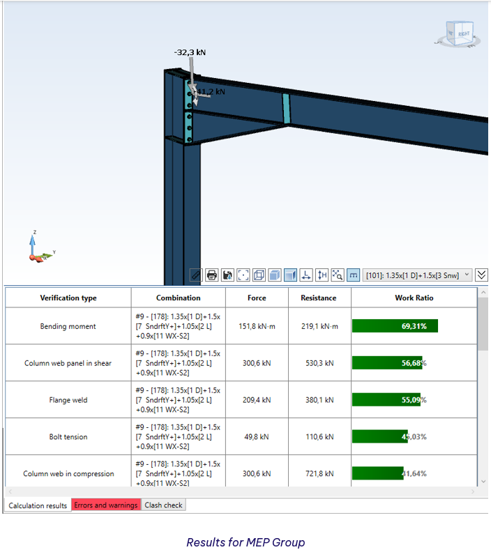
An example of the MEP Connections will be shown further.


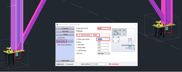
The geometrical configuration of the connection is similar to the standalone application but accessible from one single button on the ribbon: Geometry.

The Geometry button is regrouping in the Advance Design environment all the independent dialogs from the standalone application, in one dialog with multiple tabs.

The GUI of the tabs is identical to the one from the standalone module, offering the user the same smooth experience.

After the geometrical configuration is set, the Design Settings must be checked to make sure everything is according to the user project.

In the Design Settings, one particular option will define with which efforts the joints will be designed, the Combinations option. This option offers two possibilities: All Combinations or Envelopes.

All Combinations – the joint will be calculated with all existing combinations. Depending on the number of combinations, and in this case the number of connections grouped, the calculation can take longer than usual. For example, if we have 10 connections and 100 combinations, 1000 calculations will be performed.

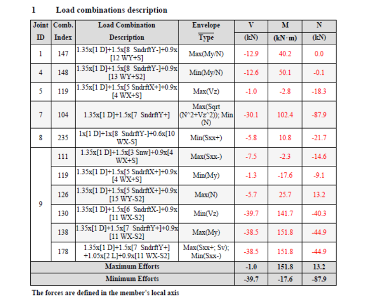
Envelopes – the joint will be calculated with the combinations that provide the maximum efforts. The criteria to choose these combinations are different from one type of joint to another and will be always available in the Report under the chapter Load Combinations description.

For the MEP group, we are showing in this article, these are the criteria and the corresponding envelopes used to verify all the connections from the same group. As we can see, instead of 100 combinations for each joint, we have only 11 envelopes.

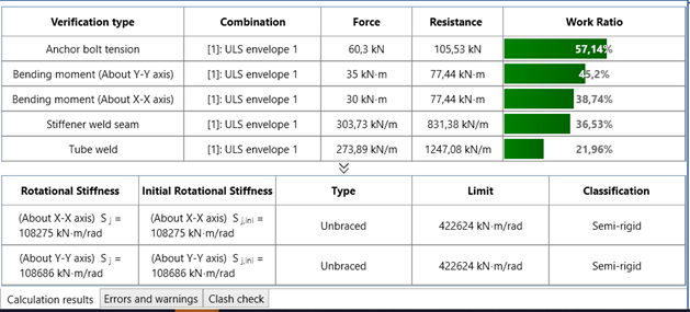
Once the Design settings are defined, the calculation can be run and the main results will appear in the console of the module. In case of warnings or/and errors, the corresponding tab will be highlighted.

If everything is ok, the drawing can be generated. This is done automatically while clicking on the Interactive Drawing tab available in the top left corner of the main window.

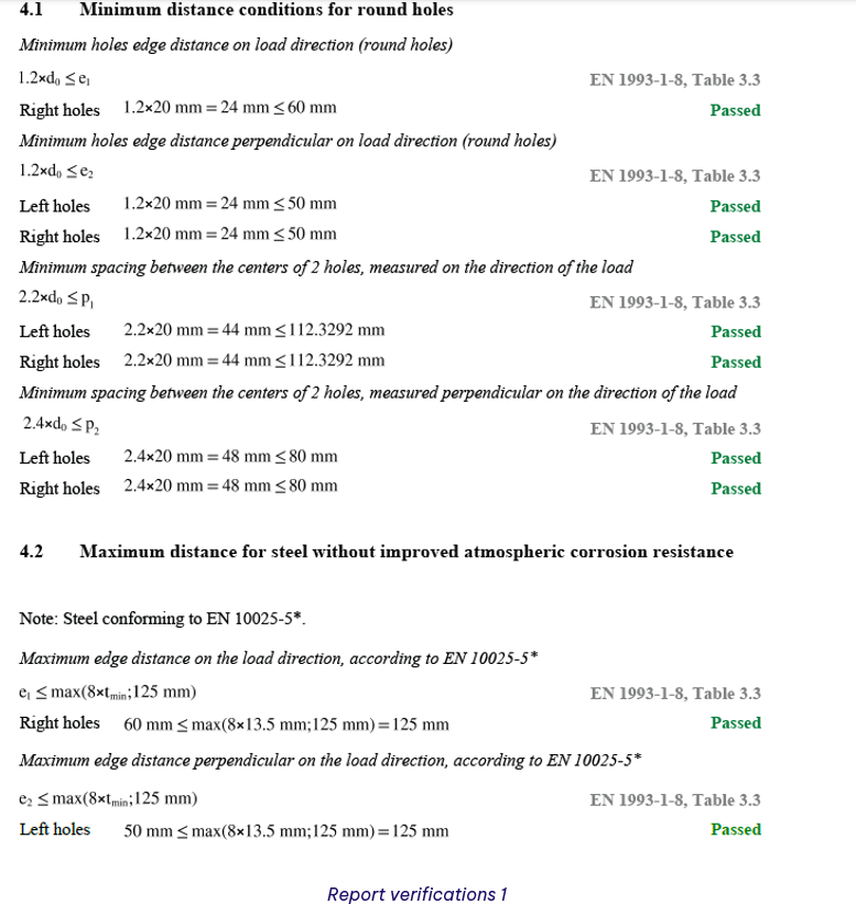
The report generation is similar to the standalone module. On the Ribbon, we have the Report Settings button, which allows the configuration of the content we want to have in the report. Here, the user can choose what chapters to include in his report.

Next to the settings, the Generate Report button is available. The report can be generated in PDF or DOC format, depending on the needs of the user.

Learn more about Advance Design!

Visit website – https://graitec.com/advance-design/
Visit Advance Design Virtual Stand – https://graitec.com/advance-design-virtual/
Linkedin – https://www.linkedin.com/showcase/advance-design-&-advance-design-connection/
Free trial – https://graitec.com/free-trial/

Advertisement

Advance Design Steel Connection – part I The Basics


by Adriana Gherlan
Steel PowerPack Manager

Abstract

This article is the first one in a series of 3. In this series you will find basic information about Advance Design Steel Connection: what it is, how it can be used and which are the main features of the module.

Keywords: #steeldesign #connections #advancedesign

1. The History

The Advance Design Steel Connection module is the evolution of a French local product Melody Attache. Even if today GRAITEC French customers are using the local product, because of the evolution of the software industry, Advance Design Steel Connection was born.

 As I mentioned in a previous article, the Advance Design Steel Connection module has evolved over the years, the User interface has changed, and a wide variety of steel joints can be calculated according to the EC3 norm, in a fast way, efficiently covering many of the situations that can occur in the steel joint calculation.

This evolution of the module can be translated into an embedded application in Advance Design and a standalone application module. Therefore, when a user is installing Advance Design, the steel connection module will be available as well, within Advance Design or standalone.

Old Version of ADSC

Version 2023 of ADSC

2. What is Advance Design Steel Connection

The Advance Design Steel Connection module is a specialized and dedicated module for joint design, using analytical methods according to Eurocode 3. The module is part of the Advance Design application and can be run inside Advance Design and as a standalone application.

In my last article, I have presented all the connections available in the steel connection module, connections documented in Eurocode 3, with specific analytical methods. Let’s have a brief review of the connections offered by the design module: Base Plate, Tubular Base Plate, Moment End Plate, Apex Haunch, Clip Angle, Gusset, Splice, HSS Bracing, Gable Wall End Plate.

3. How to use Advance Design Steel Connection based on environment

The Steel Connection module can be run together with Advance Design, allowing the user to design the specific connection directly from the Advance Design model without exiting the application.

Another way to use the module is as a standalone application, allowing the user to design the one by one the joints.

A. The Standalone environment

After the installation of Advance Design, besides the icon of the main application Advance Design, a folder is created: GRAITEC Advance Design modules. Inside this folder, the Advance Design Steel Connection icon is available, to launch the standalone application.

Once the application is started, the starting page will appear from where the user can set up the Localization, create a New file, Open an existing one, or select a predefined template from the available list for Types of connections.
Start Page

After choosing a type of connection, the user can start to configure it as needed. The accessible user interface offers all tools needed to achive the requirements.

Example of joint in standaloane

Configuration dialogs – Geometry

Once the geometry is configured, the design assumptions, the combinations and the loads can be set using specific dialogs.

Configuration dialogs – Design assumptions and Loads

As everything is set the calculation can be lunched and the results can be check quickly using the results bar available in the bottom left corner of the application window.

Results on standalone

As any other design module from GRAITEC, the results and all the geometrical details, including loads, can be checked in a simplified or detailed report. Also, the report can be generated in a DOC or PDF file format.

Report settings

I must specify that the detail report contains all formulas and articles pointing to Eurocod chapters.

Here below we can see an example of the Compression resistance of the column verification. As you notice, the chapters from Eurocode are listed on the right side of the report, in line with the specific verification.

Compression resistance of the column

As I mentioned at the beginning of or the article, this is the first one in a series of 3.

Don’t miss the next one, where I will talk about how to use the steel connection module in  Advance Design enviorement.

Learn more about Advance Design!

Visit website – https://graitec.com/advance-design/
Visit Advance Design Virtual Stand – https://graitec.com/advance-design-virtual/
Linkedin – https://www.linkedin.com/showcase/advance-design-&-advance-design-connection/
Free trial – https://graitec.com/free-trial/

Calculated steel connections available in Advance Design Steel Connection


by Adriana Gherlan
Steel PowerPack Manager

Abstract

In this article, you will find what type of connections can be checked according to Eurocode 3 within the Advance Design Steel Connection module

Keywords: #steeldesign #connections #advancedesign

Joint categories

The Advance Design Steel Connection module has evolved over the years, the User interface has changed, and a wide variety of steel joints can be calculated according to the EC3 norm, in a fast way, efficiently covering many of the situations that can occur in the steel joint calculation.

Part of Advance Design, the Steel Connection module ensures the configuration of a seamless solution, with the ability to manage and calculate bolted and welded joints, and with fully detailed design reports that include the calculation formulas and reference to the design code.

The joint library from Advance Design Steel Calculations is categorized according to the connection type, therefore 9 categories are available.

Type of joints

The Steel Connection module comes with predefined configurations for all categories, configurations that can help the user achieve faster the desired configuration.

1. Base Plate

The Base Plate joint is created by welding a steel plate to the bottom end of the column that is connected to the foundations through anchors. The joint can include several reinforcement plates, shim plates, or shear anchors.

The joint has predefined configurations that are categorized as:

  • Reduce base plate
  • Pinned base plate
  • Fixed base plate
Pinned base plate

2. Tubular Base Plate

 The Tubular Base Plate is created for cases when the column has a hollow section, rectangular or circular. The particularity of this connection is that the verifications are done in two directions, therefore the joint can be categorized as a 3D connection.

For this joint, 3 predefined configurations are available:

3. Moment End Plate

Moment End Plate joint of Advance Design – Steel Connection module is used to connect a beam to a column flange. Additional elements are available to customize this connection (i.e. haunches, plates, stiffeners, welds). 

4. Apex Haunch

Apex Haunch joint of Advance Design – Steel Connection is used for roof beams. It consists of two beams spliced with bolted end plates, on which haunches or plates can be attached at the top/and the bottom. The haunches are created from profiles or plates.

The connection has 2 predefined configurations: with or without external bolts, but the many other possibilities are achievable.

5. Clip Angle

Clip Angle connections are used for connecting a floor beam to another beam, or a column to a beam. The attached beam can be sloped to the main one. The angles are bolted or welded to the main beam.

The connection of the module has 5 predefined configurations which can be changed accordingly to the project needs. Besides those, models can be started from the default configuration and modified.

6. Gusset

Gusset connection of Advance Design – Steel Connection module connects bracing members using gusset plates. The number of bracing members that can be enabled can vary from one to three. For the calculation, the Advance Design – Steel Connection module implements Eurocode 3 international design standards, for all the connection components verification and parts of the connected elements.

7. Splice

Splice connection of Advance Design – Steel Connection module is often used to assure continuity for structural members (beams or columns) along their length. The splice plates can be bolted or welded to the main members. On web connections, U-shaped profiles can be used instead of splice plates.

8. Gable Wall

Gable Wall End Plate connection is used to connect a continuous beam to the top of the column. Similar to the Moment End Plate joint, additional elements are available to customize this connection (i.e. haunches, plates, stiffeners, welds). Like all the other connections, the Gable wall has some predefined configurations which can be changed according to the needs, or the default configuration can be initialized and changed as needed.

9. HSS Bracing

HSS Bracing connection of Advance Design – Steel Connection module connects bracing members with hollow sections, circular or square. The number of bracing members can vary from one to three.

As a connection from the module, it comes with 6 predefined configurations to help the user achieve faster the needed configuration.

Learn more about Advance Design!

Visit website – https://graitec.com/advance-design/
Visit Advance Design Virtual Stand – https://graitec.com/advance-design-virtual/
Linkedin – https://www.linkedin.com/showcase/advance-design-&-advance-design-connection/
Free trial – https://graitec.com/free-trial/

How to edit the same multiple joints but with a different configuration


By Adriana GHERLAN
Steel PowerPack Product Manager at GRAITEC

Abstract

In this article, you will find out how you can edit the same type of joint but with a different configuration, without grouping them.

Keywords: #PowerPack #AdvanceSteel #Joint #Graitec

1.     The concept

Often in the steel structure detailing projects, we have the situation when the same type of connection is available, but with a different configuration, even if we talk about one parameter.  Even if the configuration is different, the detailer might need to change one or more common properties of those connections.

Today, in Advance Steel this is possible with the functionalities around the “Group joints” feature, but with certain limitations. The limitations are related to the fact that the joints must be the same type and have identical configurations (master and slave behavior)

2.     Joint Multi-Edit

The Joint Multi-Edit available with GRAITEC PowerPack for Advance Steel is allowing the user to change parameters in two or more joints from the same category but with a different configuration. The joints do not need to be grouped or have any master and slave behavior.

2.1.            Criteria:

The criteria to enable this feature is to select 2 or more joints with are part of the same category: Base plate, Corner Base Plate, Gusset plate at 1, 2, 3 diagonals, Create Stiffeners, etc.

2.2.            Example:

Following, to understand better how this feature can be used, an example with the Corner Base Plate joint will be explained. 

Two columns with the Corner Base Plate joint are created but, as it can be seen, the configuration is different:

  • Different anchors
  • Different base plates dimensions
  • Shear lug enabled or not
  • Leveling plate enabled or not
Figure 1: Lateral view
Figure 2: Top view

To access the command Joint Multi-Edit:

  • Select both joint boxes
Figure 3: Selection of joint boxes
  • Right-click to open the active menu and search the “GRAITEC PowerPack Joint Multi-Edit” command
Figure 4: Right-click menu – command Joint Multi-Edit

When the command is selected, the dialog of the joint will be displayed.

Note: The configuration of the last joint selected is the one displayed in the dialog when this is opened with the Joint Multi-Edit command.

Figure 5: Configuration of the last selected joint

Now, when any parameter is changed, the change will be propagated to all selected joints for which the multi-edit command was activated.

Figure 6: Changes’ propagation – Shear lug type
Figure 7: Changes’ propagation – Base plate dimension

The command is working with any joint category from Advance Steel as well as on any joint from the PowerPack.