Recently introduced into the Graitec Stairs and Railings, deployed as part of the PowerPack for Advance Steel, is the New Lug feature for Railings. This new feature allows user to split up the infill panels for site installation, making it easier to transport and install these items if difficult site workspaces, I speak from experience here when trying to transport and install Railings with solid bar infills, can be quite a challenge in the confined space of a Stairwell.
Behind this new feature there are essential settings that can allow the user different types of configurations for the user to allow for combinations needed for full and partial assembly.
Basics of Railings Lug Activation.
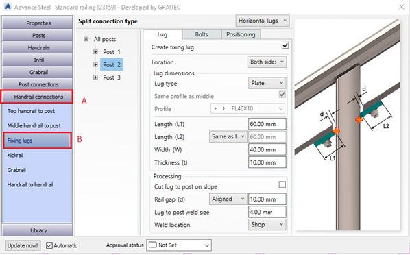
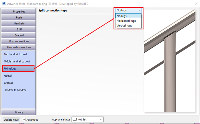
The railing lug option inside the Railing macro is available working with mid-rails to post connections, it is available under the Handrailing Connection Tab, as a sub tab Fixing lugs.
Important Setting 1
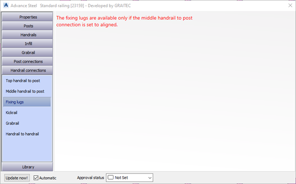
When you first go to the Fixing lugs tab you may see a dialog page that has a warning message about the availability of the lugs, this is default settings that is driven by the settings under the Middle Handrail to post Tab
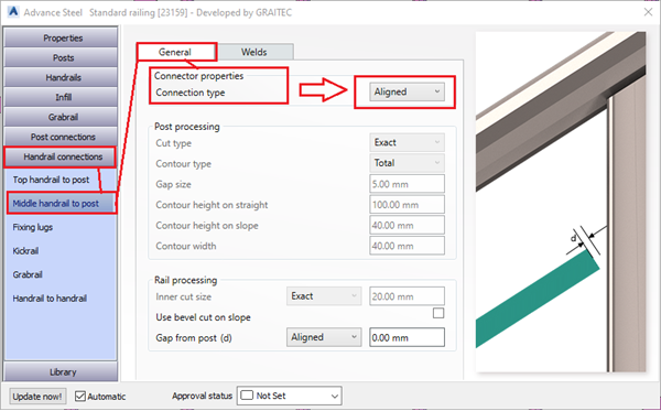
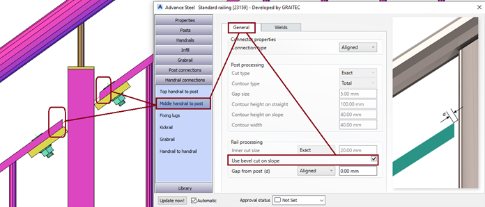
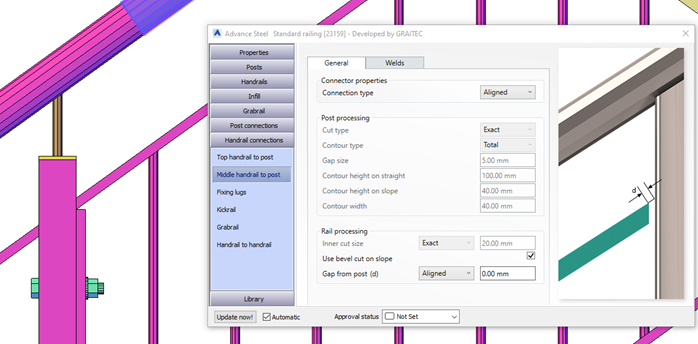
The message shown above is driven by the setting in the Middle handrail to post, from the General Tab Connection properties, connection type, the combo box must be set to Aligned.
Setting this and returning to the Fixing lugs, the user will then see the option to activate lugs for all or each post location.
On the Fixing lug page, the user will start with a combo box set to ‘ No Lugs’, changing this drop down will enable the fixing lugs, noting that the user has a choice to select which method of lugs they wish to use.
When selected the lugs are then active and the user can start changing the lugs arrangements.
Important setting 2
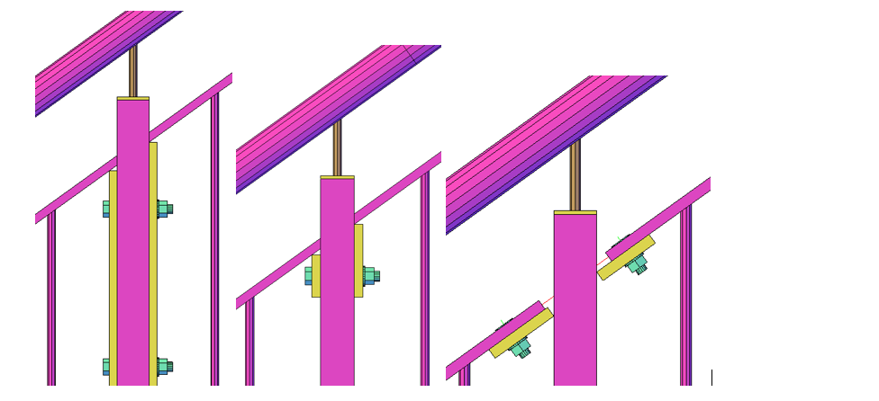
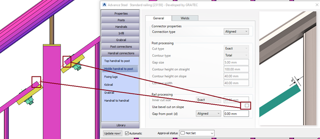
So, the user has set the lugs to horizontal, this means the lugs are positioned along the adjoining mid rail. But when we set the mid rail Connection type to aligned, then the user must look down in that dialogto change the Check box for the ‘Use Bevel cut on Slope’, unchecking this box will make the mid rail ends change to a square cut end.
Unchecking the box will change the mid-rail ends as shown in in the next image
Lug Types (tip for full vertical closure type)
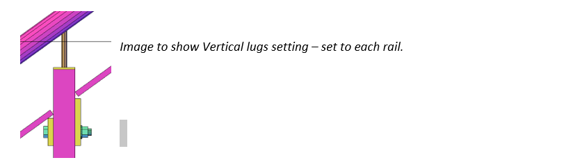
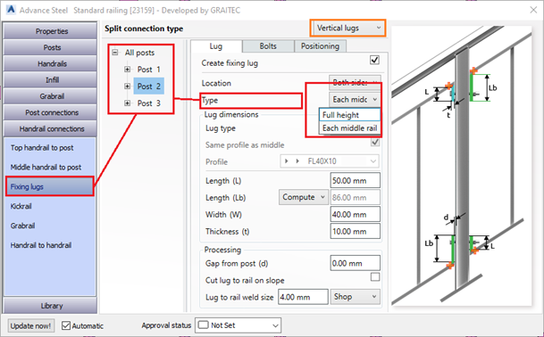
We saw in the initial drop down that the user can have both horizontal and vertical lugs, but there is another variation under Vertical type, that is a Full Vertical type. This type can be used to create an end closure to a railing panel that is bolting through and adjacent post. Useful for when railing panels are too long and need splitting into manageable sections for installation.
The user can change the basic lug type to Vertical from the initial combo box, see top of the dialog tab. Then using the Type combo box, the user will see options for ‘Each middle rail’or ‘Full Height’, Changing to full height will place a continuous vertical section at the panel end or start depending upon the location settings.
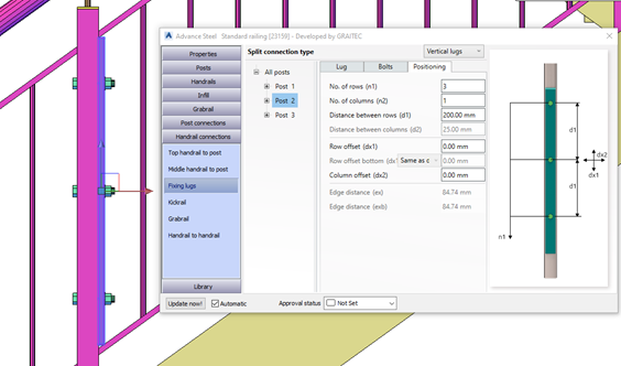
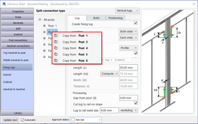
Also another nice feature of the Graitec Macro, is the dialog Tree Structure that allows the user to set the same parameters and types for all the posts in the railing panel, or for each posts, note the structure in the dialog and see that in this instance we have chosen to select Post 2 location, as we wish to split the Top rail at this location also. (split top rail is feature of the Graitec Railings.)
When this is applied you can also go back and change the mid rail ends to give a sloping cut and if required to vertical Flat Section, noting that we changed from Plate to Rolled Steel flat bar section, same as the handrail profile (Could also be different if required.)
There are many other features of the Graitec Railings macro that allow users to progress their designs efficiently and quickly and store settings that they commonly reuse within the product ranges.
Look out for more Tips of using the Graitec Railing tools in our blogs and Video postings.
June 1st we released our products for their 2022 versions, this covers the entire Graitec portfolio, well within that there are few things that stand out to me coming from the Steel detailing and design background, that sound a clear intention of Graitec in this area.
The first one is within our analysis engine ‘Advance Design’, the New feature of Cold Formed Design to EC3. This is a Game changer for those engineers using portal frame constructions and trying to design the most efficient systems for those structures.
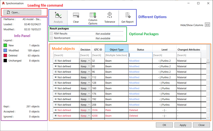
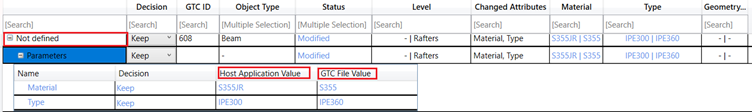
The next one is more in the link between our Advance Design platform and Autodesk Advance Steel for the transfer of model data, for this version we have a Newly design GUI and Mechanism for the Synchronization of Data using the Graitec GTCX file format. This new interface allows form many options to optimise what you wish to transfer and sync,
Figure 1-Example of new Dialog
Within the file and the options available we have the ability to have a dedicated object ID, object type, Status display for New/Modified/Deleted, Material, Geometry, Element Type.
Figure 2-example of column types
Having all these options, we now have also filter options available, to help you dig down and only see the data you require.
Figure 3- filter example.
Also, the file has now the option to contain the level of the element within the model space. It has two options to show the host location and the allocated level in the GTCX itself.
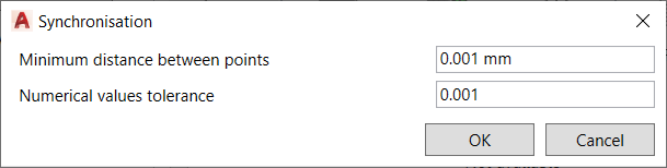
Also, all important one for model Tolerance, this allows for the user to control during the Sync process the variation between the model elements is acceptable, based upon those numeric values.
Figure 4- tolerance example
Concrete elements are now also considered for the GTCX file and the transfer, presently standard column, and beam shapes for this version, but sure other more complex shape definitions will be added to this new feature.
There are a lot more elements and options to the GTCX and the New Sync process, these are explained in depth in the what’s new, that is available to customers via the Graitec Advantage site.
Powerpack Premium Steel – Stairs and Railings
Within the premium model, particularly for Stairs and Railings we have a great new feature for those working with panelised balustrades/railings, that is the inclusion of ‘Lugs’ to the panels.
We can now add vertical and horizonal/incline lugs.
This may only look like a small feature but for those of us that have to detail these, this will be a real time saver.
Figure 5-Lugs dialog – perpendicular/incline to rail
Figure 6- Lugs – vertical to post.
Anther part of the railings in the actual placement of panels within the rail, previously there where some limits on what we could achieve, but again the development team have worked on this to improve this function to accommodate more complex arrangements.
Figure 7- complex panel shaping
This also works with the frames type panels as well.
Figure 8- framed types
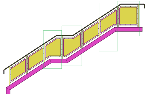
A new option is to allow for the user to turn off the top rail and still have the panels, this can be useful in the situation of external fencing panels and picket type fencing arrangements.
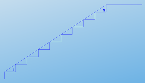
Figure 9- fencing arrangement/ Stairs/ pickets etc.
With the new release of the Powerpack for Revit 2022 we are launching the new rebar drawings generator.
In this post I am intending to explain the concept behind the tool, assumptions that were made in order to obtain the best results and at the end I will add some tips&tricks.
As you know, we already had a view generator in the Powerpack. There were 2 issues that were making the mechanism basically unusable:
The mechanism used an external Revit file that contained the drawing configurations. Therefore, there was no initial link between the user’s Revit project and our drawing template. Of course, our template could have been customized but it would had presumed some time.
In order to work properly, the rebar cage needed to be generated with the Powerpack so that rebars could have roles. After the generation, the mechanism knew the roles of the bars and knew what to do with them.
We decided to stray from this approach and we established the main pillars the mechanism will be based on:
The mechanism will be totally based on the user’s Revit Template.
It will use the active project’s view templates, detail view types and rebar schedules. It will read the Multi-Rebar Annotation, Tags and Title blocks families.
The rebar cage inside the element can be manually modelled or generated by the Powerpack.
The section of the elements will not be an issue. The mechanism will work the same for cast-in-place or pre-cast elements.
We will implement the mechanism is such a way that it will take account of the user’s browser organization sorting rules by inserting Revit’s View parameters also.
We will be able to generate wall drawings also.
In a few words, this is how the mechanism works:
Using the drawing manager, the user will make his own drawing configurations for each category of elements (Beams, Columns, Walls, Foundations)
The user will run the command and he will select the elements.
After the selection is made, the grouping algorithms will decide if the elements can be treated as a group or not.
The configuration dialog will appear, and the user is able to change the configurations.
The drawing managerSelection of elementsCreate views dialog
Using the user’s Revit Template
This part of the implementation was easy-to-do. However, during the development we ran into the issue of multiple projects. We decided to not put the user to make the drawings configurations each time he starts a new project (Assuming that users have the same revit template).
We decided to create an .xml file that will contain all the configurations made by the user. This way, the settings will always be there when the user starts a new project. Of course, modifying the Revit template to a completely different one means that you should do the configuration again.
The .xml file is placed here: C:\Users\<User>\AppData\Local\Graitec\Advance Design modules\2022\Templates\Revit\DrawingConfigs
Furthermore, with this approach, the .xml file can be shared across the office. This way only one person needs to make the configurations.
Supported elements and Rebar cages
The mechanism will work the same for any Revit Family. We are not using any mapping mechanism. Any Loadable family will be supported. Model-In-Place elements are not supported.
We established that we needed to perform the drawings regardless of the method the rebar cage was obtained (by hand or generated by the Powerpack). In order to achieve this, we needed to use the Style of the rebar shape family.
Quick recap: The style of the shape can be Standard or Stirrup/Tie. There are no geometrical differences between these two, any rebar shape can be set as either of them. The difference comes from Revit’s rebar constraints mechanism. When placing a stirrup/tie bar, it will search for the nearest host rebar cover. Standard bars will additionally search for the stirrup bars handles. Basically, the Stirrup knows that it needs to tie Standard bars. This is especially helpful when modelling rebars by hand.
Thus, we are using the style of the rebar as an input parameter in order to know on which bars we are placing Multi-Rebar Annotation or for which bars we are generating bending details.
This is probably the most important point in order to achieve proper drawings.
Example:
Rebar shape styles
Drawing manager dialog
We needed to let the user configure his drawings according to his Revit template and requirements. The dialog will manage the Annotations, Bending details (General page) and drawing configurations (Element category pages).
In the following I will explain all the options inside the dialog.
General page
Generate views only by default configuration – Checking this option will bypass the Create views dialog. The drawings will be generated according to the check at the left of the configuration in the left panel. It was intended to speed up the process.
Name – The name of the annotation configuration. It will be further used in the drawing configuration
Rebars – The rebars that the user wants to place Multi-Rebar Annotations on.
Rebar Presentation – How the users wants to show the rebars in the generated view. Examples: Central bar, three in the middle…
Multi-Rebar Annotation – The family that the user wants to use for this drawing. The list will contain all the MRA inside the project
Group MRA – If the elements has multiple distribution of the same rebar number you can group the MRA in order to obtain a single distribution symbol. Example: For a beam with stirrups distributed on 3 zones you can obtain 3 MRA or only 1 MRA.
Multiple Tag Family – On rebars that are not distributed, we are placing rebar tags using our own tag multiple bar command. The user needs to set what tag family he wants to use.
Bending detail family – What family the user wants for the generated bending details
Drawing configurations:
View type – what kind of drawing the users wants his configuration to contain. He can choose from a list that is different for each element category.
Revit view type – We used detail views for the drawings. The user can choose what detail type he wants for his drawings. We considered that this option might be used also for the browser organization. The list will contain all the detail view types in the model.
View Template – What view template the user wants to apply to the view. The list will contain all the view templates in the model.
View scale – At which scale the user wants to generate the drawing. If the view template has the scale included, the value in the dialog will be ignored.
Length ratio: Percentage of the length/height of the element at which the section/plan view/node detail will be generated.
Annotation – the annotation configuration that the user wants to use in the drawing. The list will contain the configurations from the General page
Bending detail – the bending detail configuration the user wants to apply to the view. The list will contain the configurations from the General page.
Rebar schedule category – what type of rebar schedule do you want to generate for the select element (Structural Rebar, Fabrics etc.)
Rebar schedule type – a template that will be used for the newly generated rebar schedules. The list will contain all the schedules inside the model according to the selected category.
Titleblock - A list of all the titleblocks in the model
Revit View parameters and Browser organization
Browser Organization
Advanced Revit projects are using a different browser organization rule. They are doing this with a combination of Revit View Parameters. We decided that the drawings should not be randomly generated and should take advantage of the user’s browser organization.
In order to do this, we needed to read the project’s view parameters and include them in our drawing configurations.
Add Revit View Parameters
First you need to add them into the drawing manager by clicking on the “Manage” button. Some parameters might be included in the view templates definition, so you do not need to include all of them. After adding them in the drawing manager, for each configuration, at the end of the table, new columns will be added.
Revit View parameters added to the configuration table
If you want all your drawings to have the same value for a parameter, you should insert the value into the drawing manager. However, if your values differ for each element, you should insert them into the Create Views dialog.
Grouping algorithms
Users have different ways of modelling in Revit so we needed to develop some connection algorithms that will allow us to group elements. Each element category needed to have its own grouping algorithms. Also, the grouping was made accordingly to the desired drawings.
We also took account of the design groups made in the Powerpack. Thus, if there are Multi-Span Beams or groups of Walls the user will need to select only one element inside the group.
Beams
For individual beams to be treated as a group they need to fulfill these two conditions:
They need to share a node.
Connected node in order to treat beams as a group
Their axis need to be coplanar.
Different examples for beam groups.
Grouping will allow the user to generate a full-beam elevation of elevation per each span. Sections will be placed for each span.
Columns
There are users that model columns individually for each level or who model them throughout the full height of the building. We needed to be able to obtain full column elevation. We also support slanted columns.
To be treated as a group, columns need to fulfill these conditions:
They need to be concurrent.
They need to share the same X and Y global coordinates
Column Groups
Walls
Structural walls are usually complicated drawings. They contain a lot rebars and usually they need multiple types of drawings (plan views, node details, sections, elevations and so on)
Wall groups are also different from the other element categories because they need to be grouped on 2 different planes. First they need to be grouped on the horizontal plane in order to obtain the plan view and then they need to be grouped on the Z direction in order to obtain the full elevation.
The discussion regarding the manner of modeling walls is the same from the column. They can be modelled individually or through the full height of the building, so we needed to address this issue.
In order to treat them as a group they need to fulfill these conditions:
For proper plan views:
They need to share the same Base Constraint, Base Offset, Top Constraint and Top Offset
They need to share an edge
For proper elevation:
They need to be concurrent
They need to share an edge
Wall groups
Final results:
Full beam elevation with sectionsWall drawings
Final Tips&Tricks
Pay attention to rebar styles (Standard and Stirrup/Tie)
I recommend making dedicated View Templates to each element category. This way you can automatically hide unwanted rebars or sections
You can use multiple bending details tags
You can use this tool also for the initial views the user needs to have in order to place the rebars. Generating drawings without multi-rebar annotations and bending details will be instantly done. You can use this in your advantage.
Revit allows you to place bars in a structural element in a very flexible way. This gives a great flexibility for placing rebar in a host, or to model bars of any shaping. On the other hand, it also possible to model an unfeasible shape because basically, Revit do not contain many for constructive dispositions. However, some concepts exist such as concrete cover, which can be respected (with some additional tools when placing the bars).
Figure 1 – Concrete Cover boundaries
When it comes to the shape of the bar itself, Revit allows you to create bars with no length limit. Thus, it is possible to create very long bars, without taking in account a maximum bar length for example.
Figure 2 – Example of straight bar with a high value of length in Revit.
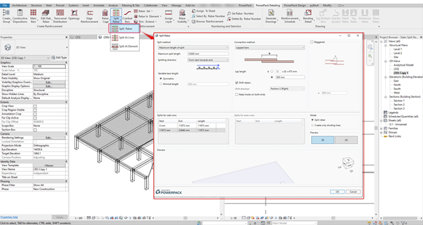
The PowerPack Detailing allows you to address this topic with the Split Rebar command.
From a bar set distribution, this command will allow the distribution to be split according to different method.
Figure 3 – Split bar command interface
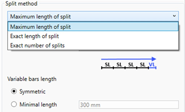
Several options to configure the splitting of the bars are possible with this dialog box but two are mainly impacting on the result:
The method of splitting bars with three options proposed.
Figure 4 – Split bar method
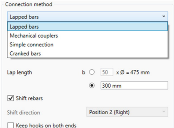
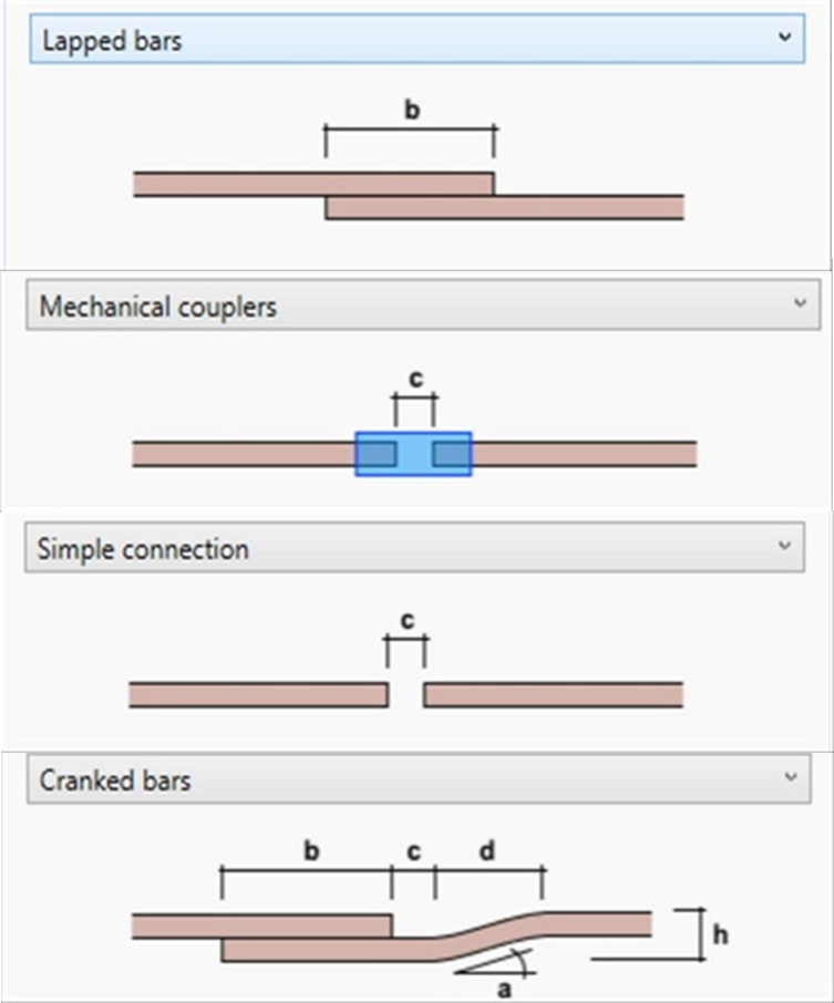
2. The method of connection for splitting bars with four options proposed
Figure 5 – Connection bar method available
In addition, an option will allow the user to create an alternate distribution after splitting the rebar set.
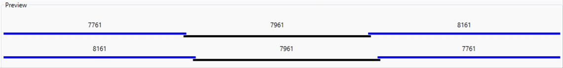
Figure 6 – Staggered option and preview
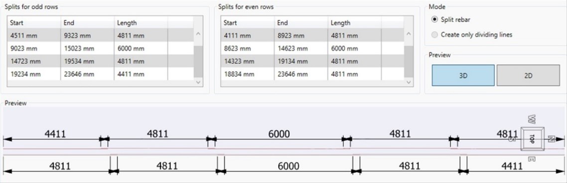
Whichever splitting method is chosen, it will be possible to choose the direction of the cut and manage the distribution of each segment.
Figure 7 – Example of setting with splitting direction
The possible configurations by this tool are therefore very important. It is just needed to select the rebar set to get the result.
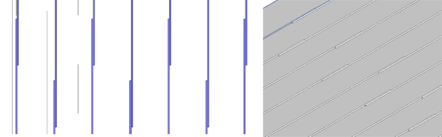
Figure 8- Example of staggered repartition with lapped bars
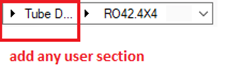
One of the benefits of the Railing macros, available in PowerPack for Advance Steel, is that the library of profiles used to create the railing can be extended.
In other words, the user can add any section to the Railing macros from the Stairs and Railing Vault.
This feature is available starting with version 2021.1 of PowerPack for Autodesk Advance Steel.
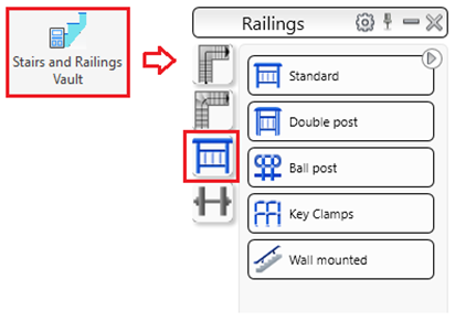
Stairs and Railings Vault
All the Graitec railing macros can be configured to use records from the Autodesk Advance Steel AstorRules database – JointsGUIAllowedSections table. This behavior is like some Advance Steel standard joints.
This flexibility of the macros offers the users to go beyond existing restrictions and extend the list of available sections in the profile selection controls, for each type of main railing element such as:
post
top rail
middle rail
kick rail
Profile selection control inside the dialog
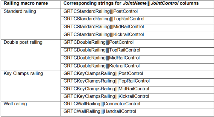
To make this work, the following strings (names) for the JointName and JointControl columns in the table, for each railing macro and each main element type inside the macros, must be used:
How it works?
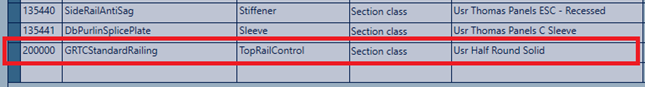
Open the Table Editor from MANAGEMENT TOOLS – AstorRules database – JointsGUIAllowedSections table.
Create a new table entry for the desired user section.
Add a new entry inside JointsGUIAllowedSections table:
Example: add half round solid sections to be used for the top handrail inside the Standard railing macro
New entry in JointsGUIAllowedSections table
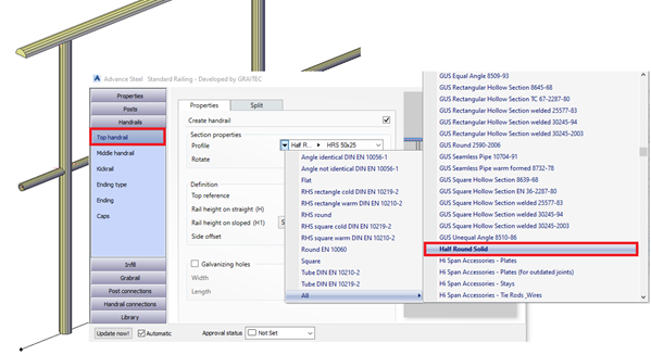
Update the database and reload it in Advance Steel using the Reopen database option. Next time the Standard Railing macro is opened, the new type of profile section can be used inside the railing:
The Stair macros available with PowerPack for Advance Steel are powerful tools for anyone who wants to create stairs, but they are not magic.
To get the best from these macros it’s important to understand the philosophy of how it’s working. This philosophy is based on 4 aspects that you must have in mind before using the macro.
Let’s start with the first one.
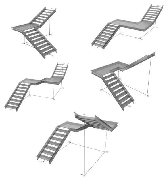
A. The 2D setting out points defined
To ensure the macro works as expected, you need to have the 2D setting out points defined.
This is an important step to be done before starting the modeling.
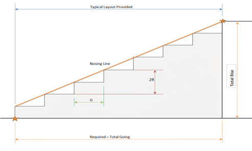
The PowerPack Premium Stair tools use different setting out points. You need the bottom point of the first tread & top point of the last tread, exactly how is showed in the image below.
B. Don’t forget about the overlap
If your stair has a constant overlap, then move your last point horizontally to include the overlap.
In the example below the overlap is 50mm, therefore the blue point was moved with 50mm.
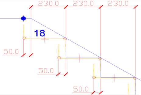
C. Know the length of the landing extension
For the staircases with 2 or 3 flights you need to know the length of the landing extension before using the macro.
In the example below, you can see 2 landing extensions for a stair with 2 flights: one of 230 mm in blue and the second of 460 mm in red.
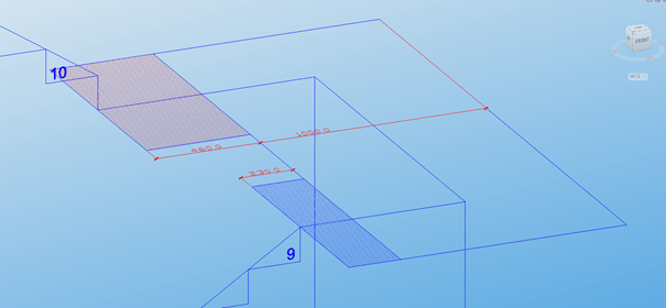
D. Turning points for multiflight stairs
For the multiflight stairs created with the PowerPack macros, you need to define the turning points at the ground level, as you can see in examples below.
Going through these 4 steps before starting to use the Stair macro, will ensure that the macro is working as you expected and you will get the full benefits of its features.
As a very common assumption for numeric models made In Revit, multispan beams are modelized as a series of colinear individual beams.
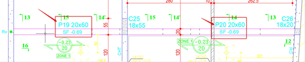
Thus, it’s make it easier for users to produce the formwork drawings, especially when placing beam tags which could include a mark number. This mark number (visible on the identity data in Revit Properties windows) could be set as unique per element, depending the codification rules of the project. It is possible to place the same value for several objects but in this case, the number indicated in the tag will be the same for all objects containing the same mark number.
Figure 1 – Mark Number filled in Revit
In addition, for quantity take off, bill of materials trough Revit schedules, it is more practical and accurate to create several single beams for each span in Revit, rather than one single very long beam.
Figure 2 – Example of multispan beams, with two different mark numbers.
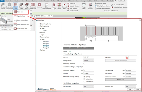
Graitec PowerPack propose through the Main bars command, a powerful wizard dedicated to reinforce structural elements such as columns, footing, walls or beams. This wizard proposes advance settings to define directly a full and complete 3D rebar cage instead of placing the bars one per one.
Figure 3 – Main bars command interface applied to beam.
Figure 4 – Example of reinforced beams generated with Main bars command
Nevertheless, to be reinforced as multispan beams, colinear beams should be consider as one, especially for the connection between to beams if we want to generate the appropriate reinforcement including a good management of the area connecting the two beams.
So, at this stage, users are often dealing with a dilemma between having on one hand a right formwork model composed of individual beams (enabling a good numbering identification for tags and good formwork quantities) and the other hand, having a long single beam for all the spans (which will be closer better to prepare the reinforcement part and not practical for the formwork model management).
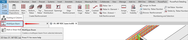
To satisfy all requirements for having a good formwork model and a good model, compliancy with our tools to generate the appropriate rebar cage, Graitec PowerPack propose a specific command named MultiSpan Beam.
Figure 5 – MultiSpan Beam command
This command will create a specific shared parameter (named “G.Beam Continuity Group”) to all individual beams supposed to be part of the same multispan serie.
It will assign the same value for this shared parameter so that the Main bar command (dedicated to create the rebar cage) will understand that this group of beams as to be consider as one multispan beam. Users just have to launch the command and select the beam belonging to the same multispan serie.
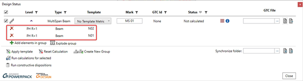
Figure 6 – MultiSpan Beam name in Revit properties
Once the selection of beam is done and validated, we can see in the dialog box all the beams which are going to be group in a reinforcement point of view. The Mark Number is indicated as well, and it is still possible to adjust the selection by removing elements or adding new ones.
Figure 7 – Multispan Beam definition
With this command, users could keep continue to model beams as individual beams and then, will be able to use our Main Bar command as a 3D rebar cage generator. The reinforcement of a selection of beams will be then consider as multispan. Main Bar will automatically detect the spans and users could switch to one span to another one, to define the reinforcement for each span individually.
Figure 8 – Main bar command launch on a multispan beam
With this command, the right reinforcement will be then generated for the extremities of the span and for each connections of the intermediate beams composing the span.
Figure 9 –Multispan beam reinforced with Main bars command
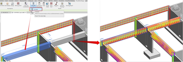
This notion could be also use for Graitec structural Design engine embedded in Revit, centralized in the ribbon PowerPack Design. The purpose of those tools is to launch design directly in Revit.
Figure 10 – Geometry command from PowerPack Design tab
The command Geometryopen a dialog bow where each span corresponding to each individual beam are visible and recognized correctly by the software. Here, users could change section and control the geometry of each span without affecting and modifying the whole span. Thanks to this, after selecting just one beam and using the Calculate command from the PowerPack Design tab, the software will calculate the complete multispan beam with the adapted reinforcement assumptions and generate the full rebar cage.
Figure 7 – Reinforcement for multispan beam, generated by design input and calculate command from PowerPack Design tab
Multispan Beam is a very practical command, easy to implement in your current workflow and which will really speed up the 3D rebar cage reinforcement generation based on your custom formwork model.
GRAITEC, an international BIM and CAD software developer for AEC, and Autodesk® Platinum Partner in US and across Europe, is delighted to announce the launch of Advance PowerPack for Autodesk® Revit® 2018, compatible with both Autodesk® Revit® 2017 and 2018.
GRAITEC is constantly improving its products to provide first-rate productivity tools for its valued customers, and the recent launch of the PowerPack for Autodesk® Revit® 2018 is no exception to this rule, as it delivers a set of new powerful tools, as well as several improvements to the existing toolset to help boost productivity in Revit®.
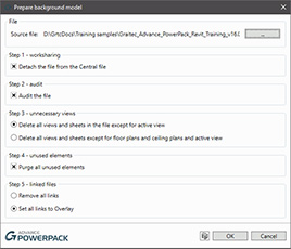
In version 2018 of the PowerPack, cleaning up your architectural background files before linking them to structural or MEP models has never been easier with the new Prepare Background Model command in the Files group.
The Link Background Model function is another powerful new tool, that links the architectural background file in the MEP or Structural model, allows users to transfer project standards from the linked file, enables copying scope boxes from the background file and make the link room-bounding.
The third new addition to the Files group is the Create Views command, which rapidly and efficiently creates views based on view templates, allowing multiple levels/view templates selection.
Prepare Background Model
Link Background Model
Create Views
One of the major changes in this version is the migration of the Reinforcement panel from PowerPack for Revit ribbon to the Reinforced Concrete BIM Designers application, as a result of users demand for a more compact reinforcement package, that includes calculation, cage generation, drawings, reports and detailing, from a single set of tools.
Another ribbon-related change involves the addition of the new category of structural modeling tools, used for verifying and correcting the analytical model of Revit projects and obtaining correct FEM results after exporting them into Advance Design.
The new tools in the set are used for resetting manual adjustments of analytical models (Reset Analytical Models), automatically trimming/extending the extremities of close objects (Trim or Extend), stretching the closest extremities of selected elements to a reference point (Stretch to Node), or indicating elements that seem to be connected but from a calculation point of view are not (Detect Errors).
Version 2018 also comes with two new modeling tools: Join & Unjoin Geometry, which automatically joins, unjoins or switches the join order of selected element categories, and Pipe insulation, which automatically assigns insulation to the systems based on parameters such as the outer or inner diameter, or assigns a specific value.
Other important improvements and news include the new interface in Russian, as well as the custom installation packages, which allow individual installation of certain PowerPack functionalities, such as Family manager, Link to Excel and Watermark Manager.
Joseph Pais, GRAITEC Products Director adds: “We are constantly encouraged by the excellent feedback and productivity gains reported by Revit PowerPack users around the globe.
The latest enhancements and new functionality that Revit PowerPack 2018 delivers stem from the proactive and rapidly growing community of users. Our vision match with our customers will help make Graitec Revit PowerPack the most powerful set of productivity tools available for Revit users in keeping with our strategy to become a global leading BIM provider and combining Autodesk and GRAITEC technologies to deliver real benefits to customers“.
With BIM adoption in full swing in the UK and America and emerging mandates across Europe gearing towards Building Information Modelling, we are pleased to announce that our Graitec Advance PowerPack for Revit review on the Engineering.com website has been voted at 4th place in the top 10 Revit content 2016 by Revit News.
As an established international software developer of a variety of BIM tools, Construction software and Structural Design Analysis solutions, the Graitec Advance PowerPack for Revit has been made available with support in multiple languages and has been designed to deliver Revit users with powerful tools that enhance productivity for many day to day design and modelling tasks for example a Revit to Excel Link, Batch Export to DWG facility, Revit Family Manager, Renaming and numbering tool and so much more.
Achieving independent recognition for our software is very welcoming indeed as it shows we are continuing to provide productive solutions that meet our clients daily needs.
The Advance PowerPack for Revit is available free of charge for Graitec’s subscribers or can be purchased if required.
Discover how you can bi-directionally link a schedule from Revit to Excel with the GRAITEC PowerPack for Revit!
As you may know, having the ability to bi-directionally link a schedule from Revit to Excel has always been extremely difficult and limited.
But with the linking tool in Revit, the user can now export a schedule from Revit and maintain a link to the file, giving the user the ability to make non-dimensional changes to the excel sheet and have the Revit parameters automatically update.
Join us on the 13th January 2017 at 3:30pm for a free webinar and learn about the Link to Excel feature and more in the GRAITEC PowerPack for Revit.
AUGIWorld is the official magazine of Autodesk User Group International (AUGI), distributed on a monthly basis to all AUGI members around the world.
In the June 2016 edition, Gareth Spencer, BIM Consultant working for GRAITEC and certified professional in Revit Architecture and Structure, presents the advantages of using GRAITEC Advance PowerPack for Revit for enhancing concrete detailing. Gareth explains the necessity of modeling reinforcement in the 3D Revit model, and introduces the GRAITEC Advance PowerPack for Revit as a versatile add-on for Revit, which can help users work more efficiently.
Gareth presents some of the most useful tools in PowerPack, such as:
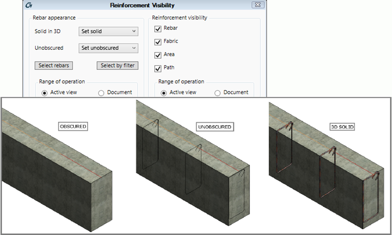
Rebar Visibility, used for changing the view’s visibility state, so as to show rebar unobscured and/or as solids in 3D views, or for hiding certain elements;
Copy Rebar, allowing users to select element rebar, and then copy it to an identical or similar element with no reinforcement assigned;
Transversal Distribution, which automatically generates transversal rebar sets with multiple spacing for linear elements.
Trim/Extend, used for adjusting the created reinforcement to the shape and particularities of the host element, in a quick and intelligent manner.
These useful new tools are complemented by several commands and functionalities for increasing productivity while working in Autodesk Revit:
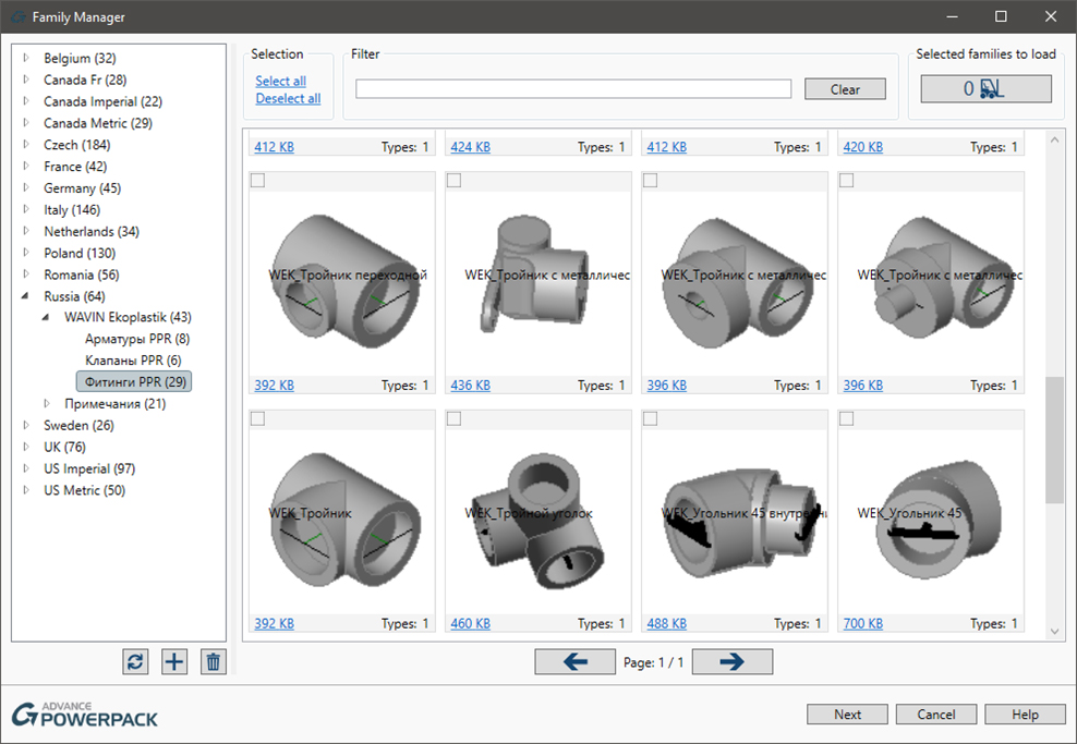
Family Manager, used for managing Revit families (by searching, selecting or filtering family lists to select the desired families to be imported in a project), either on a local computer, or in a company network;
Family Exporter, allowing users to select and export all families at once, or select desired families from the list;
Auto Section Box, which automatically creates a 3D view of the selected elements, and even duplicates it;
Dimension Annotations, a set of tools for automatic generation of dimension lines for overall dimensions, grids, external geometry, structural, and openings.
GRAITEC, international BIM and CAD software developer, announced today that following the rapid success of the PowerPack for Revit®, which has seen more than 3000 licences delivered worldwide in just over one year, GRAITEC has opted to reduce the annual subscription price of the PowerPack for Revit® to below $150 per user. This move comes as an effort to make the PowerPack for Revit® more accessible to a wider Revit® user-base and to further accelerate uptake of its Revit® add-on worldwide.
Carl Spalding, GRAITEC Product Strategy Director comments: “The PowerPack for Revit® has proven more successful than we could have predicted. Our initial objective was to offer the PowerPack for Revit® as a loyalty benefit exclusively for our Revit® subscription customers. This remains the case today and continues to differentiate GRAITEC from other Autodesk resellers. However the demand from users outside the territories in which we operate – and those from where we do operate but are perhaps locked into contracts preventing them from switching their subscription – quickly identified that we were missing an opportunity to address the needs of a much wider user-base.”
The current version of the PowerPack for Revit® offers over 60 practical tools covering a broad spectrum of basic and advanced everyday user-needs. With tools for browsing and loading families graphically, converting libraries of 3D CAD files to Revit® Families, quickly placing and displaying rebar in concrete elements, even password protecting your personal Revit® Families and so much more. Now every Revit® user across the board can easily identify one or more PowerPack tools that will address a laborious process.
Customers who have already purchased the PowerPack for Revit® will also benefit from the change as they will see their subscription fee reduced to the new price on the anniversary of their contract renewal.
GRAITEC Product Strategy Director continues: “Revit® users from all disciplines are constantly looking for tools to help them become more productive. After trawling the web and narrowing the possible options to a handful, the final decision often comes down to price. We are confident that no other tool-kit for Revit®, or any combination of individual tools for the matter, comes close to the value offered by our PowerPack, not only in terms of its deliberately low price but more importantly, because of the variety and practicality of the quality tools offered.”
Carl concludes: “GRAITEC is well known for its ambitious growth strategy and the PowerPack for Revit® is another example of how disrupting traditional practices and adding more emphasis on the value of customers is helping us move closer to our goal. Our aim is to deliver unrivalled solutions to real-world challenges, and in a way that we believe is almost impossible to replicate. The decision to revise the price of the PowerPack for Revit® will enable us to address the needs of more Revit® users and increase recognition of the GRAITEC brand worldwide. The new annual subscription fee of the PowerPack makes it a no-brainer for any Revit® user, regardless of the size, type or location of their company.”
As an approved Autodesk developer partner, GRAITEC has created a wide range of add-ons for Autodesk products for over 25 years.
Useful Links:
Discover what others are saying about the PowerPack for Revit®:
Autodesk® Advance Steel 2017 provides new features and enhancements to help improve productivity and usability whilst creating your fabrication documents more easily with tools to support a connected BIM workflow.
With new connections and profiles for international suppliers, more tools for cleaner documentation, options to manage Fabrication status data, and the ability to synchronise not just the structure but also the fully parametric steel connections with Revit, not to mention the ability to publish, share and collaborate with BIM360 using native Advance Steel drawing format – and whilst remaining connected to the source Advance Steel 3D model, Autodesk® Advance Steel 2017 delivers a more mature solution to create better coordinated designs and documentation.
Whilst Autodesk® Advance Concrete 2017 provides a more robust environment for completing and detailing concrete projects with links to Autodesk® Revit® for enhanced BIM centric workflow that supports an end-to-end solution.
Advance Steel is complimented with the GRAITEC PowerPack adding more functionality and further automating common repetitive tasks. PowerPack for Advance Steel can be downloaded directly from the Autodesk App Store as a free trial.
Other complementary solutions for Advance Steel available from GRAITEC include:
Steel Structure Designer – Create, adjust and configure complete structures of all shapes and sizes in minutes.
Ball Post Railing Designer – Adding ball post railings in Advance Steel is quick and simple with this dedicated ball post railing app.
Complimentary Reinforced Concrete design and detailing tools from GRAITEC include:
PowerPack for Revit – over 40 new tools dedicated to reinforced concrete modelling, editing and documentation.
Carl Spalding, Product Strategy Director comments: “It is clear BIM is transforming how teams collaborate and build their projects across the globe. The Autodesk 2017 products are certainly ahead of the curve in delivering solutions to support their user’s needs for BIM centric workflows. This is evident from the harmonised structural steel workflows possible between Revit and Advance Steel dramatically reducing the initial design and rework effort for steel modelling and detailing.”
Carl continues “But this is just the tip of the iceberg. The biggest trend we are experiencing comes from the concrete sector frantically looking to replace traditional 2D detailing systems, which often break the BIM to fabrication workflow causing inevitable bottlenecks, with practical BIM-centric reinforced concrete solutions. The new reinforcement capability in Autodesk 2017 products, combined with complementary Add-ons and Apps from Graitec, demonstrate our commitment to delivering every-day reinforced concrete tools that support a BIM workflow. Looking ahead users can benefit from robust structural BIM workflows which promote the reuse of engineering BIM data, otherwise ignored when transferring project models, to enable structural projects to be completed more efficiently directly within Revit.“
GRAITEC, international BIM and CAD software developer for AEC, and Autodesk® Platinum Partner in US and across Europe, is delighted to announce the next instalment of the popular add-on for Autodesk® Revit®, GRAITEC Advance PowerPack, which now includes a considerable range of tools for reinforced concrete modelling and management.
The PowerPack for Revit® includes many tools that generally aid daily practices making it very attractive for any Revit® user looking to save time and improve their experience, but the latest version of the PowerPack for Revit® includes even more general productivity tools aimed at improving every-day use that make it extremely hard for the even the most experienced Revit® user to ignore.
The biggest difference in this release however, is the introduction of an impressive range of practical tools and functionality around reinforced concrete modelling and documentation. GRAITEC clearly aims to strengthen its presence in the structural sector and, by delivering essential tools to manage rebar in Revit®, entice both users of traditional 2D RC systems and their Autodesk® Advance Concrete users to migrate seamlessly to Revit®.
Carl Spalding, GRAITEC Product Strategy Director, comments:“Revit® is widely recognised as the go-to product for BIM modelling and is fast becoming a robust multi-industry BIM platform. GRAITEC strategy is to become a leading worldwide BIM technology provider, combining our and Autodesk technologies to deliver real benefits to customers and accelerate BIM adoption around the world. These latest additions to the PowerPack for Revit® will bring speed and efficiency to modeling rebar in Revit® and make the world of BIM for reinforcement considerably more accessible to the market and Revit® community”.
In its short time, the PowerPack for Autodesk® Revit® from GRAITEC, has quickly become a well-established add-on, adopted by thousands of Revit® users worldwide and it is clear GRAITEC is committed to providing tools that hone in on the needs of Revit® users from all industries. Here are a few examples:
A slick window arranger which allows all active window views to tiled, easily adjusted and all views cantered.
Simple dialogue to change the visibility state showing or hiding reinforcement in an element.
Expand area reinforcement to slabs of any irregular shape in one operation.
Quickly create, explode, adjust and divide Rebar sets
Project browser allows you to quickly show or hide elements in the model by instance or category.
Password protect your Revit® families with a secure watermark with the Watermark Manager.
And many more…
More over the PowerPack tools are conveniently grouped into categories and saved on their own ribbon which can be easily accessed by switching between Ribbons using the dropdown menu “Ribbon Customization”.
A free trial version of the GRAITEC Advance PowerPack for Revit® is available to download from the GRAITEC PowerPack web page, and an updated trial version will also soon be available on the Autodesk Exchange App Store.
A full license of the PowerPack for Revit® can be purchased directly from your local GRAITEC office or representative and from the Autodesk Exchange App Store – when approved, or included as a no-cost benefit to customers who purchase or renew their Revit® subscription contracts through GRAITEC.
Updated Glass Panels
• Insert multiple glass panels at once
• Use any profile shape or material
• Easily define single and multi-layered glass
• Create a reusable library for windows, railings and structural glass
Cut a straight tube, plate or folded beam by a curved tube
Fully control the cut contour
Easy to set and amend:
Number of points
Weld type and thickness
Cut offset
Contour shape
The GRAITEC PowerPack is a powerful extension to Autodesk® Advance Steel, designed to boost the user’s capability, productivity and efficiency. This PowerPack builds on the strength of the marketing leading Autodesk® Advance Steel by introducing a set of unique tools, templates and connections intentionally designed to enhance and speed up project delivery.
Create corrugated beams with this new feature
• Easily create a beam with an undulated web
• Use either a beam from the catalogue or user defined
• Control all dimensions that define the beam
GRAITEC, international BIM and CAD software developer for AEC and all round structural industry specialist, is delighted to deliver even more tools in the latest version of the Advance PowerPack for Autodesk® Advance Steel 2016.
The new version of GRAITEC’s Advance PowerPack for Autodesk® Advance Steel includes a wealth of functionality and productivity tools to ensure customers achieve a true competitive advantage when using Autodesk® Advance Steel 2016.
The latest version, which is in addition to all previous tools, introduces several new connections, tools for setting out complex helical stair stringers, links with cloud services and a suite of commands for transforming Advance Steel drawings into AutoCAD compatible versions, whilst retaining intelligent scaled and editable dimensions.
GRAITEC customers receive the PowerPack for Advance Steel as a complimentary addition to their Autodesk® Advance Steel subscription and service contract, or it is available to purchase separately from GRAITEC or one of our global partners.
Carl Spalding, GRAITEC Product Strategy Director comments: “Initially the PowerPack was a way for us to deliver additional tools and unique value to customers. The rapid adoption by users around the world and the incredibly positive response has been very impressive. Each version introduces more tools, more automation, and more functionality enabling customers to boost their output and improve quality. It is encouraging to see how the tools we provide can make such a massive difference and it is no wonder the PowerPack is quickly becoming the must-have tool of a busy and competitive design office.“
Improved Beam Commands for faster, smarter working
• Draw continuous beams the same way as a poly line
• Add and adjust rotation angles
• Adjust all beams at once
• Simple selection and fine tuning of parameters
• Add continuous beam sections in a single session
• Easily define and adjust all sections from the dialog box