How to edit the same multiple joints but with a different configuration


By Adriana GHERLAN
Steel PowerPack Product Manager at GRAITEC

Abstract

In this article, you will find out how you can edit the same type of joint but with a different configuration, without grouping them.

Keywords: #PowerPack #AdvanceSteel #Joint #Graitec

1.     The concept

Often in the steel structure detailing projects, we have the situation when the same type of connection is available, but with a different configuration, even if we talk about one parameter.  Even if the configuration is different, the detailer might need to change one or more common properties of those connections.

Today, in Advance Steel this is possible with the functionalities around the “Group joints” feature, but with certain limitations. The limitations are related to the fact that the joints must be the same type and have identical configurations (master and slave behavior)

2.     Joint Multi-Edit

The Joint Multi-Edit available with GRAITEC PowerPack for Advance Steel is allowing the user to change parameters in two or more joints from the same category but with a different configuration. The joints do not need to be grouped or have any master and slave behavior.

2.1.            Criteria:

The criteria to enable this feature is to select 2 or more joints with are part of the same category: Base plate, Corner Base Plate, Gusset plate at 1, 2, 3 diagonals, Create Stiffeners, etc.

2.2.            Example:

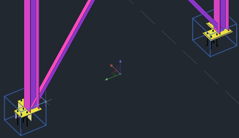
Following, to understand better how this feature can be used, an example with the Corner Base Plate joint will be explained. 

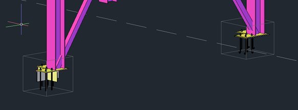
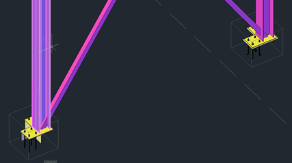
Two columns with the Corner Base Plate joint are created but, as it can be seen, the configuration is different:

  • Different anchors
  • Different base plates dimensions
  • Shear lug enabled or not
  • Leveling plate enabled or not
Figure 1: Lateral view
Figure 2: Top view

To access the command Joint Multi-Edit:

  • Select both joint boxes
Figure 3: Selection of joint boxes
  • Right-click to open the active menu and search the “GRAITEC PowerPack Joint Multi-Edit” command
Figure 4: Right-click menu – command Joint Multi-Edit

When the command is selected, the dialog of the joint will be displayed.

Note: The configuration of the last joint selected is the one displayed in the dialog when this is opened with the Joint Multi-Edit command.

Figure 5: Configuration of the last selected joint

Now, when any parameter is changed, the change will be propagated to all selected joints for which the multi-edit command was activated.

Figure 6: Changes’ propagation – Shear lug type
Figure 7: Changes’ propagation – Base plate dimension

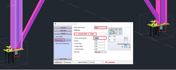
The command is working with any joint category from Advance Steel as well as on any joint from the PowerPack.

Advertisement

How to find out the start point and direction a beam was created in advance Steel 2018


While searching the forum, I found an intriguing question and I thought I would create a short video to address the issue.

Here is the dilemma, you are working on many projects simultaneously. While jumping from one project to another, you notice that in some of the drawings, your beam orientation is not as you expected.

It would be great if, in the steel structure, you were able to find out the start point of the beam. Did you create the beam from left from right or right from left?

TIP: Advance Steel allows you to view what direction the beam was created.

Open the Advance Steel Tool Palette and select the UCS category, which is the fourth icon in the first column.  Within that category select the second icon called “Define coordinate system” in the third row.

After selecting the beam in question, you will find a symbol as seen in Figure1. The symbol shows you that this beam was created from right to left and in Figure 2 the beam was created from left to right.

How to find out the start point and direction a beam was created in advance Steel 2018

Figure 1

How to find out the start point and direction a beam was created in advance Steel 2018

Figure 2

How to have Advance Steel 2018 recognize and use a customized Prototype that was created in the default location


Woah, I’m using the American installation of Advance Steel 2018. I’ve opened the Prototypes folder located in C/ProgramData/Autodesk/Advance Steel 2018/USA/shared/Support/Prototypes.

I copied an existing prototype and created a custom Prototype (Title block), for my company and saved it in this default location of Advance Steel.

I create drawings and Advance steel is using the Prototype, aka Title blocks from the default setup not my customized Prototypes. I get a warning that says “Prototype not found.”

How can I have Advance Steel recognize my custom Prototype?

Advance steel is able to recognize you custom prototype, however you need to map it to the correct Drawing process.

Please watch the video to view the steps to have Advance Steel 2018 recognize and use a customized Prototype that was created in the default location.

How to create a handrail to an existing stair and anchor it to a concrete wall using the wall rail tool in Advance Steel 2018


With Advance Steel 2018, you can now create a wall rail on concrete.

The wall rail tool is located on the Extended Modeling tab, Structural Elements panel. This video will show how to accomplish this.

Simply move the UCS to the face of the concrete, position the orientation of the X and Y axis accordingly, use the view on UCS tool and turn on your 2d snaps located on the Quick views category of the Advance steel tool Palette.

Create a line where you want the wall rail to be. In this video the system line of the stringer and landing was used.

Use the wall rail tool to create and customize the rail. Tweak the railing using the options located on the General, Wall Plates, Connections and Rail Segments panels. You can then save the customized railing in the library located on the Properties panel for later use.

How to change the slope dimensions to display in inches or only degree


Here is the issue, you have created a drawing which have sloped dimensions on it. You want the dimensions to display in inches rather than feet. Perhaps you have a client that wants to have the slope dimensions displayed in degrees rather than inches. How do you accomplish this in Advance steel?

This can be done locally on each drawing sheet, however, what if you have the same scenario on hundreds of sheets?

Not to worry. You can make the changes globally and have the changes reflect the created sheets after updating the database and using the force Update for the drawing or by updating the drawing in question.

How to change the piece marks that have an incorrect Phase number


Here is the dilemma, you have created a structure in phases and notice that some elements of the structure don’t reflect the phase. In fact, the piece marks are displaying the wrong phase number in the Model browser and the drawings they were created on.

What do you do, certainly not renumber the entire structure?

Advance steel allows you to remove the numbering and information from the problematic elements using the Toggle switch display SP/MP tool located on the Output tab, Part marks panel.

Watch the video for more info

Video | How to change multiple elements through the model browser


This video shows how to add a model role to multiple elements using the model browser.

The model browser is a powerful tool that allows you to browse, filter, check, and edit your model. You can select certain elements in the browser and isolate them, only these elements will be visible in the structure.

Through the model browser, you can see if a part has been numbered or if it has been assigned a model role.

Add columns for specific criteria regarding Main and single part mark, Main and single part prefix, material, coating.  It is possible to add coating or change Section sizes by putting a check in the Edit properties located in the upper left corner of the window.

Video | How to create claddings in Advance Steel


It is easy to create claddings to a specified area of a structure using the Advance Steel cladding tools, located on the Extended Modeling tab, Structural elements panel. Similar standard panels can also be used for decking.

Simply place the UCS accordingly then define the cladding area using the “Define cladding area tool” once the area is defined create any cut outs or openings using the “Define cladding opening tool”.

Once these parameters are defined you can now create the claddings using the “Create cladding tool”.

Within the properties dialog box, you will find an extensive library of cladding and decking sections where you can adjust the orientation and finishing properties as well as the placement offset, cut per slope and much more!

The 4th Annual Advance Steel Academy 2017 in US is a Success!


Thank you to everyone who made our Annual Advance Steel Academy a success! We are already planning ahead for next year’s event in Baltimore!

The 4th Annual Advance Steel Academy 2017 in US is a Success!

GRAITEC, Autodesk® Platinum Partner, hosted its fourth edition of Advance Steel Academy, an advanced training focused on Autodesk® Advance Steel. This event took place in San Antonio on March 20-22, just before the NASCC, and we welcomed 50 Advance Steel users (this number has doubled from last year!). “The objective of the Advance Steel Academy is for all attendees to develop their Advance Steel skills, learn about trends within the building and construction industry and network with other industry professionals.” Hugo Michaud, Sales Director Americas, Graitec Group.

The first day was met with a buzz of excitement at the historical Menger Hotel as we anxiously awaited our guests’ arrival.

This was my first Advance Steel Academy to attend, and I will continue attending in the future. I learned new tips, tricks and technics on most all seminars. Networking and socializing with fellow Advance Steel users and the tech team proved to be quite beneficial as well. I recommend it to all Advance Steel users!” Lewis Moreland, Owner, EZDrawLLC

The GRAITEC team welcomed Autodesk Advance Steel users with different backgrounds. Steel and Precast Detailers, Steel Erectors, Steel & Precast Fabricators, Structural Engineers, Contractors, etc. gathered for in-depth workshops, technical sessions and networking.

For the third consecutive year, we were joined by Autodesk partners. Michael Gustafson, Industry Strategy Manager for Structural Engineering at Autodesk, talked about Autodesk’s vision for the Future of Structure & BIM. He adds: “Graitec’s Advance Steel Academy event was a big success. I’ve attended this event for three years now, and it has steadily attracted more customers each year. It was a great week having the opportunity to meet with Advance Steel customers at Graitec’s event as well as at NASCC.

The 4th Annual Advance Steel Academy 2017 in US is a Success!

Udo Haedicke, Advance Steel Product Manager, gave an exclusive preview of the new 2018 features. He comments: “What a nice event. Thank you for getting the chance to promote the new features of Advance Steel and the opportunity to chat with so many great customers!

This was my second Advance Steel Academy and it was great. The perfect opportunity to discuss problems, learn new tricks, exchange ideas and share solutions with the Advance Steel experts as well as other users.” Matt Steiger, Detailer/CAD Manager, Mountainview Steel Detailing

Continue reading…

Video | How to Reference Connections Created by Camera to a Key Plan View


Using Advance Steel Cameras at node tool, it is easy to create drawings of connections in your structure and reference them to a plan view.


First define the camera symbol presentation. How do you want the camera symbol to be displayed on drawings?

This can be done from the (ASMT) Advance Steel Management Tools by selecting the Defaults category. Use the filter option and type “Camera in the field.”

Select the detailing camera representation type from Drawing-Presentation sub category > General.

Place the UCS at the level where your connections are located, “Create cameras(s) at node” tool and define the camera direction.

By using the Drawing Process, “Cameras”, you have the option of “Selected cameras” or “All Cameras”.

Choose your required sheet size and the details are automatically created.

From the Drawing style GA Plans, Elevations/Sections category you can choose a ready-made template.

Select the elements you want included on the plan view and the drawing is created with the camera referenced to the plan view.

Advance Steel Academy 2017


2017_01_24_image_user_group.jpg (680×284)

Our annual Advance Steel Academy (formerly Advance Steel User Group) is coming up March 20-22, 2017 in San Antonio, TX. For new Advance Steel users who may not have attended in the past, and those who want to know what’s new for this year’s event, have a look at the agenda!

  • Learn features within Advance Steel software that will add great value to your steel detailing process
  • Learn from experts and learn more about the industry than just your day-to-day operations
  • Network with others in the industry, including notable Autodesk leaders
  • A full-day focus on customizing your output (drawing styles)
  • The event takes place the same week and location as the NASCC. Get a free pass!

Learn more and register

Free webinar: how to boost productivity and shorten project life cycles when detailing stairs & railings


Discover how Advance Steel boosts productivity and shortens project life cycles when detailing stairs & railings on our free webinar!

Register today to get an insight into how the software can be utilised for architectural metalwork detailing with a particular focus on using glazed components within the stair structure.

Discover how Advance Steel boosts productivity and shortens project life cycles when detailing stairs & railings on our free webinar!

Join our technical specialist to see how we can use the Advance Steel toolset to add a glazed staircase complete with customised sections for the stringers and glazed panels for the railing components. In this masterclass we will show the key modelling techniques involved and how to get the best from the software.

The webinar will conclude with a Q&A session with our technical specialist.

Webinar Host: Nial Ball
Date: 30th August 2016
Time: 10:00 AM – 11:00 AM


Register your place today!

GRAITEC helps bridge the gap between analysis, design and fabrication


Synchronization of structural model from Autodesk Advance Steel to Advance Design America


GRAITEC technology ensures a more connected BIM workflow and helps bridge the gap between analysis, design and fabrication.

This video shows how to synchronize a structural model from Advance Steel, Autodesk ‘s structural steel detailing software (based on AutoCAD platform) to Advance Design America, Graitec’s structural analysis and design software.

Using the GTCX file format, the user can transfer the model from Autodesk Advance Steel to Advance Design America and perform the analysis and design procedure. It is also possible to modify the geometry or sections to optimize the structure.

Then the model in Advance Design America can be easily sent back to Autodesk Advance Steel including all the internal forces coming from the load combinations. The user will be able to design or verify the connection design and detailing based on the forces coming directly from analysis and design software.


Watch the video on YouTube: https://youtu.be/MyD3C6xIeuI

If you need any information regarding Advance Design America or Autodesk Advance Steel, please call Graitec on 1-800-724-5678

Email us at info.americas@graitec.com or fill out the form here

Advance Steel 2017 & Advance Concrete 2017 now available


GRAITEC, an international BIM and CAD software developer for AEC, and Autodesk® Platinum Partner in US and across Europe, is pleased to announce that Autodesk® Advance Steel 2017 and Autodesk® Advance Concrete 2017 are now available from Autodesk.

GRAITEC, an international BIM and CAD software developer for AEC, and Autodesk® Platinum Partner in US and across Europe, is pleased to announce that Autodesk® Advance Steel 2017 and Autodesk® Advance Concrete 2017 are now available from Autodesk.

Autodesk® Advance Steel 2017 provides new features and enhancements to help improve productivity and usability whilst creating your fabrication documents more easily with tools to support a connected BIM workflow.

With new connections and profiles for international suppliers, more tools for cleaner documentation, options to manage Fabrication status data, and the ability to synchronise not just the structure but also the fully parametric steel connections with Revit, not to mention the ability to publish, share and collaborate with BIM360 using native Advance Steel drawing format – and whilst remaining connected to the source Advance Steel 3D model, Autodesk® Advance Steel 2017 delivers a more mature solution to create better coordinated designs and documentation.

Whilst Autodesk® Advance Concrete 2017 provides a more robust environment for completing and detailing concrete projects with links to Autodesk® Revit® for enhanced BIM centric workflow that supports an end-to-end solution.

Advance Steel is complimented with the GRAITEC PowerPack adding more functionality and further automating common repetitive tasks. PowerPack for Advance Steel can be downloaded directly from the Autodesk App Store as a free trial.

Other complementary solutions for Advance Steel available from GRAITEC include:

  • Steel Structure Designer – Create, adjust and configure complete structures of all shapes and sizes in minutes.
  • Ball Post Railing Designer – Adding ball post railings in Advance Steel is quick and simple with this dedicated ball post railing app.

Complimentary Reinforced Concrete design and detailing tools from GRAITEC include:

  • PowerPack for Revit – over 40 new tools dedicated to reinforced concrete modelling, editing and documentation.

Carl Spalding, Product Strategy Director comments:It is clear BIM is transforming how teams collaborate and build their projects across the globe. The Autodesk 2017 products are certainly ahead of the curve in delivering solutions to support their user’s needs for BIM centric workflows. This is evident from the harmonised structural steel workflows possible between Revit and Advance Steel dramatically reducing the initial design and rework effort for steel modelling and detailing.

Carl continuesBut this is just the tip of the iceberg. The biggest trend we are experiencing comes from the concrete sector frantically looking to replace traditional 2D detailing systems, which often break the BIM to fabrication workflow causing inevitable bottlenecks, with practical BIM-centric reinforced concrete solutions. The new reinforcement capability in Autodesk 2017 products, combined with complementary Add-ons and Apps from Graitec, demonstrate our commitment to delivering every-day reinforced concrete tools that support a BIM workflow. Looking ahead users can benefit from robust structural BIM workflows which promote the reuse of engineering BIM data, otherwise ignored when transferring project models, to enable structural projects to be completed more efficiently directly within Revit.

Video: Advance Steel Interoperability with Graitec Advance Workshop


This video shows how to quickly and accurately round trip fabrication information between Autodesk Advance Steel and Graitec Advance Workshop software. You will see:
– what information is exchanged between the two products
– how Advance Workshop utilizes this information in fabrication management
– how changes are synchronized and visualized using colorization of the 3D model in Advance Steel

BIM Workflow – Autodesk® Advance Steel > Autodesk® A360 Drive


Jonathan Hand, Software Application Engineer at GRAITEC, speaks about exporting an Advance Steel model to A360…

Autodesk A360 enables design and engineering centric project teams to work efficiently together in one central workspace.

A360 online viewer allows you to combine and connect data to better create, view, analyze, share, and manage information on your structural projects By exporting a completed Advance Steel model to ACIS we can upload the project to A360.


Check out my screencast video showing whats possible with the new features in A360. With every model uploaded you will now have a 2D view and also use the section tools to cut the model in any required axis.


You can follow the link bellow to see the video:
https://screencast.autodesk.com/Embed/50579b5e-3826-47c8-819f-1d42c8bbc91b

GRAITEC’s First North American Autodesk® Advance Steel User Group


From June 09 to 11, 2015, GRAITEC is organizing its first North American Autodesk® Advance Steel User Group in Salt Lake City, Utah.

GRAITEC’s First North American Autodesk® Advance Steel User Group

Supported by Autodesk and local industry specialists, the User Group aims to provide an advanced training to all GRAITEC Advance Steel customers. They will assist to technical presentations and experience Autodesk® Advance Steel and GRAITEC solutions 2016 versions. It will help them go deeper in some of the major functions and tools, get a clear understanding of the software’s full potential and interact with other industry professionals.

From June 09 to 11, 2015, the User Group will address a wide range of topics including:

  • Autodesk® Advance Steel 2016
  • Drawings Styles Customization
  • Management tools database
  • Stairs and Railings
  • GRAITEC Advance Workshop, the new MIS Solution for Steel Fabricators integrated with Autodesk® Advance Steel
  • GRAITEC PowerPack for Autodesk® Advance Steel, the powerful extension designed to boost the user’s capability, productivity and efficiency.

To attend this event, click here

We look forward to seeing you there.

Advance Steel Project: Pedestrian foot bridge


Pedestrian foot bridge of University Campus at Brno Bohunice

Pedestrian foot bridge of University Campus at Brno Bohunice

Software used: Advance Steel
Project location: Brno, Czech Republic

Design Office: OKF s.r.o.
Architecture Office: A PLUS BRNO a.s.
Contracting Authority: MU Brno + AIG/LINCOLN

Project description:
The footbridge serves as a connection between Masaryk University in Brno, University Campus Bohunice (UCB) and the BRNO CAMPUS SQUARE (BCS) shopping center. The main support beam consists of orthotropic steel deck plates with integrated drainage troughs. Four sloped beams made from welded tapered rectangular cross sections are fixed into the reinforced head of every pillar. The cladding of the footbridge is made from bended composite sheets called BOND, or from fiberglass in the part above the trolley wire.

Graitec Test Drive Autodesk Advance Steel


Get hands-on experience of Advance Steel
3D modelling software for steel detailing
Register for a FREE Test Drive today!


Better understand how you can boost your productivity and reduce errors & omissions.
Register for an Autodesk Advance Steel Test Drive today!

Autodesk Advance Steel provides structural steel detailers, fabricators, engineers and contractors with a comprehensive suite of tools for 2D and 3D detailing of structural elements, steel connectors and plates. Together with the Graitec PowerPack; which has enhanced tools and functionality for faster modelling, users can experience Autodesk Advance Steel and get a competitive advantage and improved project workflow.

Graitec is pleased to announce its upcoming series of FREE Advance Steel Test Drives, which will help you better understand the benefits of using the software compared to regular AutoCAD or 2D based solutions.

Learn direct from the Advance Steel Application Engineers

Register for a FREE Test Drive today!

Register for a half-day event and see how purpose-built tools and customisable standards help streamline the design process.

Using intelligent structural objects with a built-in steel connection design engine, you will have hands-on software time to create a structural building, complete with connections, railings and stairs.

As design changes are made, drafting and construction documentation will update automatically; helping to boost productivity and reduce errors and omissions.

Advance Steel software uses building information modelling (BIM) to help structural engineers and designers evaluate more ‘what-if’ scenarios earlier in the design process. Automatic fabrication and general arrangement drawings ensure accuracy, along with integrated revision control ensuring full control over all documentation.

If you are using regular AutoCAD or similar software, this is a great opportunity to better understand how you could benefit from the new technologies offered by Advance Steel.

The Graitec ISV team will run each event from 9.30am-12.30pm, which will be held at each of our UK offices. Dates are:

⇒ Wednesday 8th April – Southampton Office
⇒ Tuesday 14th April – Nottingham Office
⇒ Thursday 16th April – Durham Office
⇒ Wednesday 22nd April – Bradford Office

⇒ Thursday 23rd April – Milton Keynes Office

Booking is easy! Register today!

To register a place, simply visit graitec.co.uk/events-form


If you wish to discuss the test drives in greater detail or to discuss any other aspect of your CAD, BIM or IT requirements, feel free to contact us on (023) 8086 8947.

Places are FREE, but are extremely limited, so reserve your place now to avoid disappointment.

Southampton
Riverside House
Brunel Road
Totton,Southampton
Hants
SO40 3WX
T: (023) 8086 8947
Bradford
Quayside House
Salts Mill Road
Shipley, Bradford
West Yorkshire
BD18 3ST
T: (01274) 532919
Durham
Chancery Court
Belmont Business Park
Durham
County Durham
DH1 1TW
T: (0191) 374 2020
 

Nottingham
Sherwood House
Gregory Boulevard
Nottingham
Nottinghamshire
NG7 6LB
T: (0115) 969 1114


Milton Keynes
Cranfield Innovation Centre
University Way
Cranfield
MK43 0BT
T: (01908) 410026

Advance Steel Project: Exhibition hall


Exhibition hall “P” in Brno Exhibition Center

Project location: Brno, Czech Republic
Software used: Advance Steel
Design office: OKF s.r.o.


Project description:
The biggest exhibition hall in Central Europe with a free standing area of over 20000 m2 (steel frameworks of 2400 tons) holds a modern exhibition hall and a new entrance to the exhibition center. The steel load-bearing skeleton is composed by trusses with frame installations on both of its ends. The west-facade, made of glass supported by the steel sub-structure, represents the window-case in contrast with the simple geometry of the latest generation sandwich-panel cladding.
The analysis model used for the structure design was continuously updated with Advance Steel. The Advance Steel model was used for creating the steel structure documentation and also for creating the fabrication drawings of the steel structure, which integrate a significant amount of cladding sub-structure parts.
One of the main benefits of using Advance Steel for this project is that the tube diagonals were manufactured directly from the 3D model exploded to ACIS solids.
Also, the documents created with Advance Steel dramatically contributed to the short creation time required for this project.

Technical information:
Weight of the steel structure: 2 400 tons
Bund-up area: 20 000 m2