
Product Technical Specialist
Abstract
In this article, we will apply the methods from EN1996-1-1, Annex C to estimate the out-of-plane eccentricity of loading on a masonry wall subjected to mainly vertical loading.
Keywords: Advance Design, Masonry, Eurocode 6, EN1996-1-1
1. Introduction
The vertical load coming from a floor connected on top of a masonry wall is usually eccentric.
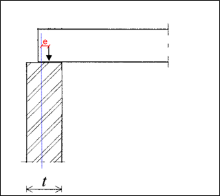
As a result, this eccentric force will create an out-of-plane moment on top the wall that must be properly assessed. Annex C from EN1996-1-1 provides two methods in that regard. In this article, we will apply each method on an example, and we will compare the obtained moment.
2. Moment on top of the wall
Annex C from EN1996-1-1 provides two methods to assess the out-of-plane moment on a masonry wall:
- First method, in Clause (2), is based on the stiffness of the connected members (floors and walls)
- The other method, in Clause (6), relies on a simplified expression
Although quite intimidating, the method based on the stiffness of the connected members from eq. (C.1) is said to be less conservative and therefore, more cost-effective.
We will compare both methods on a given example.
2.1. Assumptions
We will calculate the moment on top of the lower wall in the configuration below:

- Walls
- Thickness: t = 0,2m
- E = 3192 MPa
- Level height: H = 2,70m
- Boundary conditions: Fixed
- Slabs
- Thickness: t = 0,2m
- E = 30 000 MPa
- Clear spans: L = 6m and 2,5m
- Boundary conditions: Fixed
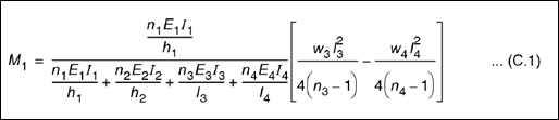
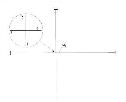
2.2. First method – Stiffness of the connected members
The first method uses a simplified frame model where members 1 and 2 respectively stand for the upper and lower walls, while members 3 and 4 stand for the left and right floors.
Moment is then calculated from eq. (C.1):

Where:
- h1 and h2 are wall heights
- l3 and l4 are the clear spans of the connected floors
- w3 and w4 are the distributed loads on the adjacent floors
- ni are the stiffness factors of each member (taken as 4 for members fixed at both ends and 3 otherwise)
All inertias are equal due to all members having same thickness (0,2m):
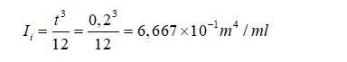
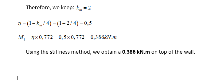
Eq. (C.1) can then be simplified:

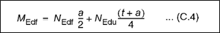
2.3. Second method – Simplifed expression
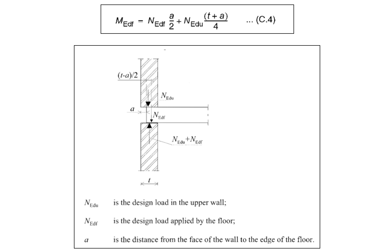
The second method relies on a simplified expression

3. Conclusion
The method based on the stiffness of the connected members from Clause (2) appears to be less conservative indeed.
Yet, the gain turns out to be minimal most of the time.
Therefore, the simplified expression from Clause (6) is usually the preferred method, especially for manual calculation.
Fortunately, our upcoming Advance Design module, dedicated to masonry wall design, will instantly apply both methods and retain the minimum moment value, ensuring an optimum design for your masonry projects.
Learn more about Advance Design!
Visit website – https://graitec.com/advance-design/
Visit Advance Design Virtual Stand – https://graitec.com/advance-design-virtual/
Linkedin – https://www.linkedin.com/showcase/advance-design-&-advance-design-connection/
Free trial – https://graitec.com/free-trial/
