Buckling Verification of an Angle Section


by Thibaut Frette
Product technical specialist

Abstract

In this article, we will design an Angle section in pure compression, considering its principal axes (u-u & v-v).  

Keywords: Advance Design, Angle, Eurocode 3, EN 1993-1-1

1.Introduction

ke most steel structural members, angle sections are designed not in their geometrical axes (y-y & z-z, parallel to the legs) but in their principal axes (u-u & v-v).

2.    Theory

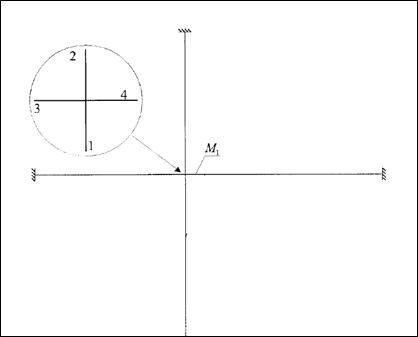
The Eurocode 3 convention for member axes refers to the axes about which the moment acts.

For most sections, that would be the geometrical axes (y-y & z-z):

  • y-y is the cross-section axis parallel to the flanges
  • z-z is the cross-section axis perpendicular to the flanges

Yet, this convention is not suitable to angle sections, for which bending occurs about the principal axes (u-u & v-v).

Therefore, the u-u & v-v axes should be used instead:

  • u-u major principal axis
  • v-v major principal axis

3. Application

Assume a L 90×9 equal leg angle, subjected to a NEd = 80 kN compressive axial force.

Steel grade is S275.

The effective slenderness (λeff) refers to annex G from EN1993-3-1:

EN1993-3-1 (Annex G)

The effective slenderness involves a k parameter, which depends on the type of restraint, as per Table G.2 from EN 1993-3-1.

For buckling about the v-v axis though, the k formula is unchanged.

Table G.2 from EN1993-3-1

The angle section under consideration is properly designed.

4.     Conclusion

Angle sections should be designed about their principal axes, especially in pure compression situations, where buckling typically arises about the v-v axis.

The upcoming update of Advance Design (version 2023.1) will enable this option, while letting the user consider the effective slenderness ratio.

Learn more about Advance Design!

Visit website – https://graitec.com/advance-design/
Visit Advance Design Virtual Stand – https://graitec.com/advance-design-virtual/
Linkedin – https://www.linkedin.com/showcase/advance-design-&-advance-design-connection/
Free trial – https://graitec.com/free-trial/

Shelter factor for walls and fences at the Eurocode 1


by Thibaut Frette
Product technical specialist

Abstract

In this article, we will compute the shelter factor that applies to a free-standing wall to account for the presence of an upwind wall or fence.  

Keywords: Advance Design, wall, free-standing wall, Eurocode 1, EN1991-1-4, return corner

1.Introduction

In a previous publication, we have covered the determination of wind forces on a free-standing wall at the Eurocode 1:  

https://civil-engineering-design.com/2022/07/19/wind-action-on-free-standing-walls-at-the-eurocode-1/

The present article goes one step further by considering the interaction between several walls, and the sheltering effect they may produce on each other.

In addition to these supports, a user defined nonlinear support mechanism is also possible (“NL-Diagram” option in Figure 2).

2.    Theory

Shelter factor is defined in §7.4.2 from EN1991-1-4.

This coefficient will reduce the pressure coefficients when an upwind wall is able to provide protection to the wall under consideration.

The shelter factor can be determined on Figure 7.20, based on:

  • The spacing between the two walls (x)
  • The solidity ratio of the sheltering wall (φ)
  • The height of the sheltered wall (h)

3. Example

Assume a 15m x 4m wall, with a φ = 0,9 solidity ratio.

The pressure coefficients on this isolated wall would be:

  • Zone A: Cp,net = 1,863
  • Zone B: Cp,net = 1,375
  • Zone C: Cp,net = 1,237

Now, if a similar wall, were to be located at a 40m distance, it would produce a sheltering effect that would be introduced in the calculation through the shelter factor.

Of course, the alternate oblique wind direction should be considered as well:

The climatic generator Advance Design is able to automatically detect the potential upwind walls and to compute the corresponding shelter factor for each wind direction. 

On the picture below, Advance Design detected that the wall under consideration could benefit from the sheltering effect of an upwind wall for the Y+ wind direction, resulting in ψs=0,55.

Yet, no such walls were detected in the other directions, resulting in ψs=1,0 for the X+, X- and Y- directions.

4.     Conclusion

When designing a wall or a fence for climatic actions, the determination of the shelter factor can be a lengthy and tedious process, yet totally worthy as it can allow for a significant reduction of the wind forces.

Fortunately, in Advance Design, the detection of the potential upwind walls with the shelter factor they produce, is performed instantly during the automatic wind generation.

Learn more about Advance Design!

Visit website – https://graitec.com/advance-design/
Visit Advance Design Virtual Stand – https://graitec.com/advance-design-virtual/
Linkedin – https://www.linkedin.com/showcase/advance-design-&-advance-design-connection/
Free trial – https://graitec.com/free-trial/

Wind action on free-standing walls at the Eurocode 1


by Thibaut FRETTÉ
Product Technical Specialist

Abstract

In this article, we will apply the procedure from the EN1991-1-4 to estimate the wind forces on a free-standing wall with a return corner.  

Keywords: Advance Design, wall, free-standing wall, Eurocode 1, EN1991-1-4, return corner

1. Introduction

Free-standing walls are covered in §7.4.1 from EN1991-1-4.

This part is intended towards fences as well as buildings with so many openings that they should be designed as per §7.3 (canopy roofs) and §7.4 (free-standing walls).

2. Theory

The Eurocode 1 defines two types of free-standing walls:

  • Without return corner
  • With return corner
Free-standing walls will be divided in A, B, C and D zones, depending on how long they are.

Pressure coefficients for each zone are determined from Table 7.9 and may require up to 3 successive linear interpolations based on:

  • The dimensions of the wall (Length/Height ratio)
  • The length of the return corner (if any)
  • The solidity ratio of the wall (also called opening ratio or porosity)

3. Example – Free-standing wall with return corner

Assume a free-standing wall (Length: 16m and Height: 4) with a 0,9 solidity ratio.

This wall has a 2m-long return corner.

3.1.            1st linear interpolation
We perform a 1st linear interpolation based on the length/height ratio of the wall (ignoring the return corner).

Yet, the values we have just obtained (in red) only stand for a wall without a return corner.

A 2nd linear interpolation is then required.

3.2            2nd linear interpolation

We perform a 2nd linear interpolation based on the length of the return corner (noted L’).

Yet, the values we have just obtained (in blue) only stand for a solid wall (φ = 1).
A 3rd and final linear interpolation is then required.

3.3.            3rd linear interpolation

We perform a 3rd linear interpolation based the solidity ratio of the wall.

The values we have just obtained (in green) are the ones we should expect for the A, B and C zones (the wall is not long enough to get a D zone).

There are the values the climatic generator from Advance Design 2023 will return:

Of course, Advance Design will consider all required wind directions (perpendicular and oblique winds).

Advance Design will also consider more complex effects, such the potential force reduction that can be benefited from an upwind wall, through the shelter factor (ψs) defined in §7.4.2:

4. Conclusion

The estimation of wind forces on free-standing walls sure is a tedious process, with a high risk of errors due to the various linear interpolations needed.

Fortunately, version 2023 of Advance Design now handles these structural elements, generating the corresponding forces on your 3D structures in a single click.

Learn more about Advance Design!

Visit website – https://graitec.com/advance-design/
Visit Advance Design Virtual Stand – https://graitec.com/advance-design-virtual/
Linkedin – https://www.linkedin.com/showcase/advance-design-&-advance-design-connection/
Free trial – https://graitec.com/free-trial/

Out-of-plane eccentricity of loading on a masonry wall 


by Thibaut FRETTÉ 
Product Technical Specialist

Abstract

In this article, we will apply the methods from EN1996-1-1, Annex C to estimate the out-of-plane eccentricity of loading on a masonry wall subjected to mainly vertical loading.  

Keywords: Advance Design, Masonry, Eurocode 6, EN1996-1-1

1. Introduction

The vertical load coming from a floor connected on top of a masonry wall is usually eccentric.

As a result, this eccentric force will create an out-of-plane moment on top the wall that must be properly assessed. Annex C from EN1996-1-1 provides two methods in that regard. In this article, we will apply each method on an example, and we will compare the obtained moment.  

2. Moment on top of the wall

Annex C from EN1996-1-1 provides two methods to assess the out-of-plane moment on a masonry wall:

  • First method, in Clause (2), is based on the stiffness of the connected members (floors and walls)
  • The other method, in Clause (6), relies on a simplified expression

Although quite intimidating, the method based on the stiffness of the connected members from eq. (C.1) is said to be less conservative and therefore, more cost-effective.

We will compare both methods on a given example.

2.1. Assumptions

We will calculate the moment on top of the lower wall in the configuration below:

  • Walls
    • Thickness: t = 0,2m
    • E = 3192 MPa
    • Level height: H = 2,70m
    • Boundary conditions: Fixed
  • Slabs
    • Thickness: t = 0,2m
    • E = 30 000 MPa
    • Clear spans: L = 6m and 2,5m
    • Boundary conditions: Fixed

2.2. First method – Stiffness of the connected members

The first method uses a simplified frame model where members 1 and 2 respectively stand for the upper and lower walls, while members 3 and 4 stand for the left and right floors.

Moment is then calculated from eq. (C.1):

Where:

  • h1 and h2 are wall heights
  • l3 and l4 are the clear spans of the connected floors
  • w3 and w4 are the distributed loads on the adjacent floors
  • ni are the stiffness factors of each member (taken as 4 for members fixed at both ends and 3 otherwise)

All inertias are equal due to all members having same thickness (0,2m):

Eq. (C.1) can then be simplified:

2.3. Second method – Simplifed expression

The second method relies on a simplified expression

In case of an intermediate wall, with floor spanning on each side, the load from the wall above (NEdu) is considered to be concentric and each side of the floor is taken as supported individually by half of the total bearing length (a = t/2):

3. Conclusion

The method based on the stiffness of the connected members from Clause (2) appears to be less conservative indeed.

Yet, the gain turns out to be minimal most of the time.

Therefore, the simplified expression from Clause (6) is usually the preferred method, especially for manual calculation.  

Fortunately, our upcoming Advance Design module, dedicated to masonry wall design, will instantly apply both methods and retain the minimum moment value, ensuring an optimum design for your masonry projects.

Learn more about Advance Design!

Visit website – https://graitec.com/advance-design/
Visit Advance Design Virtual Stand – https://graitec.com/advance-design-virtual/
Linkedin – https://www.linkedin.com/showcase/advance-design-&-advance-design-connection/
Free trial – https://graitec.com/free-trial/