Application examples of nonlinear advanced supports


by Naim Ayoub
Product technical specialist

Abstract

This article presents application examples of nonlinear advanced supports. The purpose is to highlight how these supports work and the different mechanisms they have.

Keywords: Advance Design, Advanced Supports, Nonlinear Analysis.

1.Introduction

Some structures require special type of supports such as:

  • Supports that work only in tension or compression (tension or compression only supports).
  • Supports that allow displacements/rotations within specified limits. Once these limits are reached, the supports are activated and no further displacements/rotations are allowed (gap supports).
  • Supports that block displacements/rotations until specified reaction forces/moments limits are reached. Once these limits are reached, displacements/rotations are allowed while maintaining the limit forces/moments reactions (hardening supports).

Advance Design has all these special supports available in the advanced supports feature. They can be assigned to each DOF separately and are available for point, line and surface supports (refer to Figures 1 and 2)

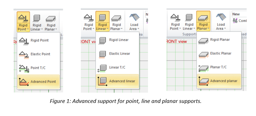
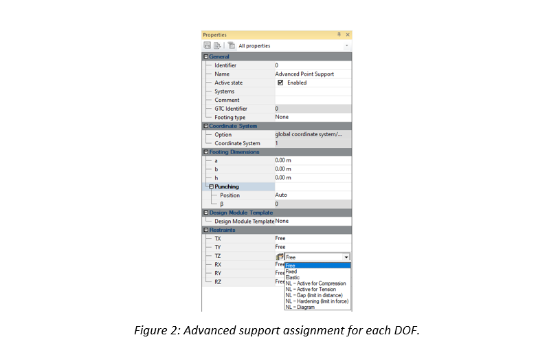
In addition to these supports, a user defined nonlinear support mechanism is also possible (“NL-Diagram” option in Figure 2).

2.     Application examples

1.1.            Gap supports

Two identical 2D frame structures are considered. A pin support is used on the left side and an advanced support on the right side for each frame (refer to Figure 3). Frame 2 carries double the load of frame 1.

The advanced support for both frames is fixed in the vertical translation and presents a 2 cm displacement gap in the horizontal translation (refer to Figure 4).

Since nonlinear supports are used, a nonlinear analysis is conducted and the results are presented in Figures 5 and 6:

In Figures 5 and 6, it is clear that for frame 1 the gap support did not reach its limit (1.67 cm < 2 cm) therefore no horizontal support force was applied to block the displacement. For frame 2, theoretically we should get twice the displacement since it carries double the load. However, the gap limit of 2 cm is reached and a horizontal support force is applied to block any further displacement.

2.2.            Hardening supports

Considering similar frame structures to paragraph 2.1. A pin support is used on the left side and an advanced support on the right side for each frame (refer to Figure 7). Frame 2 carries double the load of frame 1.

The advanced support for both frames is fixed in the vertical translation and presents a 10 kN limit hardening support in the horizontal direction (refer to Figure 8).

Since nonlinear supports are used, a nonlinear analysis is conducted and the results are presented in Figures 9 and 10:

In Figures 9 and 10, it is clear that for frame 1 the hardening support limit is not reached (8.27 kN < 10 kN) therefore the support was able to block the displacement. For frame 2, theoretically we should get twice the support force since it carries double the load. However, the hardening support limit of 10 kN is reached and it can no longer block any further displacement requiring more than 10 kN of force.

3.     Conclusion

The advanced supports are a powerful tool in Advance Design for modeling structures with particular support conditions. The user can choose between predefined support mechanisms such as gap and hardening supports or define his own mechanisms.

Learn more about Advance Design!

Visit website – https://graitec.com/advance-design/
Visit Advance Design Virtual Stand – https://graitec.com/advance-design-virtual/
Linkedin – https://www.linkedin.com/showcase/advance-design-&-advance-design-connection/
Free trial – https://graitec.com/free-trial/

Advertisement

Transfer beam analysis using construction stages


by Naim AYOUB
Product technical specialist

Abstract

This article highlights the importance of construction stages in studying frame structures with transfer beams. For this purpose, a result comparison between Advance Design construction stages and classical full model single run analysis are presented for a steel frame model with a transfer beam.

Keywords: Advance Design, Construction Stages, Transfer Beam.

1. Introduction

In conventional structural analysis, all loadings are applied at once on the complete final structure before studying their effects in a single step calculation. In other words, no loading of any type is applied on the structure until the entire construction process is completed. However, in practice, structures are constructed in stages (story by story) and loadings such as self-weight, construction and finishing loads are present at each stage prior to structure completion. Therefore, at each construction stage, the distribution of displacements and internal forces in the completed parts of the structure (due to the existing loads) is not affected by elements of upper stories that do not exist yet.

Neglecting the construction stages effect in the classical analysis will sometimes yield wrong results.  A good example where this effect should not be overlooked is in analyzing frame structures with transfer beams.

2.Frame structure with transfer beam

A steel frame structure with a transfer beam in story 1 is considered. This structure is subjected to its self-weight and finishing dead loads at each story (refer to Figure 1).

2.1.            Construction stages

Construction stages are defined according to the actual story by story construction sequence (Refer to Figure 2).

2.2.            Results comparison

To highlight the importance of conducting construction stages analysis, results comparison between the Advance Design classical analysis (all loads applied at once on the complete final structure) and construction stages will be presented (refer to Figures 3, 4 and 5).

3.     Conclusion

The real structural behavior obtained by the construction stages analysis is very different from the results of the classical analysis. Neglecting the construction stages effect, will lead to a dangerous under dimensioning of the transfer beam and middle column.

Learn more about Advance Design!

Visit website – https://graitec.com/advance-design/
Visit Advance Design Virtual Stand – https://graitec.com/advance-design-virtual/
Linkedin – https://www.linkedin.com/showcase/advance-design-&-advance-design-connection/
Free trial – https://graitec.com/free-trial/

The benefits of BIM in the field of construction


Nick Johns, Head of Digital Production for Graitec UK, gave an interview to the prestigious online magazine PBC Today, in which he explained in detail the issues regarding the adoption of BIM by manufacturers in the construction industry, suggesting the benefits it brings BIM adoption: profitability, efficiency, expanding the market share and win new tenders.

The full article can be read here.


Take a sneak peek into the brand new BIM Designers Slab Module


GRAITEC BIM Designers Slab Module provides automatic reinforcement design solutions according to international codes and norms for slabs. The module will be introduced to the public for the first time starting with the official release of the 2020 Graitec Advance Suite.

The reinforcement cages for slabs can be designed using individual bars or fabrics that can be selected from large international libraries. They can also be manually customized based on users’ preferences. The module allows designing reinforcement cages made from a mix of fabrics and bars.

Read the full article here

Take a sneak peek into the brand new BIM Designers Wall Module


BIM Designers Wall Module provides automatic reinforcement design and performs the necessary verifications according to international codes for bearing and shear walls. The module will be introduced to the public starting with the official release of 2020 Graitec Advance Suite.

The software also automatically generates drawings, diagrams, and reports. Based on the generated reinforcement cage, the Wall Module generates, with the help of the ”Bill of Materials” command, the necessary quantity of materials as well as their total estimative cost. The prices of the materials are defined by the user per unity.

Read the full article here


New features of BIM Designers 2019 highlighted by Autodesk specialists


Earlier this month, Village BIM – a blog specialized on BIM software solutions – published a review centered upon Graitec BIM Designers, a collection of advanced apps for automating structural design-to-detail BIM workflows developed by Graitec. The review is highlighting the undeniable impact of BIM Desiger’s workflow upon cost reduction.

Continue reading

5 reasons why the using of pirated software is a waste of time and money in the end


Hello guys! We had notice how many people are searching for bootleg copies of our software and though to tell you why this is hurting the users more than the companies. Often illegal downloads come from sketchy websites filled with viruses. In some cases, the only thing that the user can actually read is the download link. Don’t you think this is just a little bit crazy?

graitec advance design 2018 crack

Tip: If you want to try Graitec Advance Design 2018, just download the trial from our website.

While we had made the research for this article we found the answer of a Reddit user to a question related to the online piracy which saying that the usage of a pirated software is like “sitting on a time bomb without knowing when it will explode”. Maybe the comparison could be considerate a little bit out of the hook those days, but the point remains valid.

If you not getting his point of view right away, take a look of those disadvantages:

Continue reading

7 types of connections that can be easily design with Steel Connection Designer


Greetings dear fellows engineers! Did you know that Graitec BIM Designer Series has been split into two packages? Starting with 2018 release, the Advance BIM Designer are grouped under two series to meet the specific needs of each industry sector: Concrete Series and Steel Series. Also, the Steel Series contains the following modules: Stair & Railing Designer, Steel Connection Designer and Structure Designer.

Today, we going to focus on Steel Connection Designer*. Part of Graitec BIM Designer, the package ensures the configuration of a seamless solution, with the ability to manage and calculate bolted and welded joints, and with fully detailed design reports that include the calculation formulas and reference to the design code. The software design steel connections to Euro Codes, directly in Advance Design or as a standalone solution.

Continue reading

GRAITEC acquires Canadian Autodesk VAR PROCAD


Bièvres, France, April 2018 – GRAITEC, an international BIM, Fabrication and Design software developer for AEC, Autodesk® Platinum Partner across Europe and Gold Partner across USA, Canada and Russia announced today that it acquired 100% shares of Procad, Montreal, Canada on Wednesday April 4th . (The terms of the deal have not been disclosed.)

The acquisition of Procad reinforces the position of Graitec in Canada where the company is already operating as (1) Autodesk Gold Partner; (2) developer and reseller of 2 world standard structural analysis & design software: Advance Design and Advance BIM Designers and Advance Workshop, MIS Solution; and (3) as service provider and Research & Development partner for engineering offices and manufacturers.

Continue reading

Graitec EMEA Win Autodesk Platinum Award for Third Consecutive Year


GRAITEC, an international BIM, Fabrication and Design software developer for AEC, and Autodesk® Platinum Partner across Europe, is delighted to announce winning the  prestigious Autodesk Platinum Award for the third consecutive year, for the “Largest Net New Subscription Growth in Europe, Middle East and Africa (EMEA)”

Winning an Autodesk Platinum award is a spectacular achievement in a very challenging and hotly contested market place. But managing to achieve this accolade three consecutive years in a row is testament to a business that is clearly focussed on growth through its customer centric approach, not only helping clients achieve their own successes, but also assisting them to maximise the return on their Autodesk software investments.

Says Steve Houlder, Graitec COO: We were delighted to achieve a Platinum Award for the second-time last year. Being able to achieve our goal for a third consecutive year however is huge honour, and one that not only reinforces the chosen path for our strategic growth initiative, but also demonstrates the strength and depth of experience of all the Graitec teams across EMEA who’s commitment, professionalism and focus have helped make this achievement possible once more.


Says Manuel Liedot, Graitec CEO: “The achievement of this award clearly illustrates our determination and commitment to the goal of becoming a leading global BIM provider and principal Autodesk Partner, as we continue to invest in strengthening our teams, our technology and service delivery. I would like to congratulate all the Graitec teams involved for their hard work and dedication, as well as thanking all our loyal and new customers around the globe for their continued support.”


About GRAITEC

Founded in 1986, GRAITEC is an international Autodesk Platinum Partner across Europe including an Autodesk Developer Partner and Autodesk AEC Solution Associate, delivering high-performance BIM solutions, bespoke add-ons and apps for Autodesk key AEC platforms. Operating throughout 38 offices across 11 countries worldwide, GRAITEC offers its clients an extensive range of established software solutions combined with the full portfolio of Autodesk products and BIM suites which help address the most demanding projects needs and maximize productivity, efficiency and performance. With 450 employees amongst which there are 200 BIM consultants, GRAITEC is an innovation focused company whose products are used by more than 50,000 construction professionals worldwide.

Graitec Brings the Future of Making-Rebar in Revit to Autodesk University 2018


GRAITEC, an international BIM and CAD software developer with more than 30 years expertise in AEC, and Autodesk® Platinum Partner is proud to announce that one of its online courses made the short list of trending classes at Autodesk University.

The Future of Making-Rebar in Revit session is among the most viewed course this month, and it provides an in-depth view on automating the modeling, detailing and scheduling of structural elements within Revit in one connected workflow.

The course delivers a both engaging and comprehensive session, showing how intelligent BIM data in a connected workflow can enable structural elements (such as footings, columns, and beams) to be automatically modeled, detailed, and scheduled using Revit software.

The session includes four key learning points:

  • Connected structural BIM workflow
  • Benefits of intelligent BIM data
  • Detailed 3D rebar cages in Revit
  • A more automated finish with the use of default or custom Revit families.

The main focus lies on a more automated creation of designed 3D reinforcement cages in Revit software, with the use of default or custom structural Revit families. The course also explores the configuration of automated drawings, views, bar scheduled and design reports using standard Revit families.

Access the link below to change the way you approach designing rebar in Revit:

Graitec: The Future of Making-Rebar in Revit

Graitec Brings the Future of Making-Rebar in Revit to Autodesk University 2018


How to find out the start point and direction a beam was created in advance Steel 2018


While searching the forum, I found an intriguing question and I thought I would create a short video to address the issue.

Here is the dilemma, you are working on many projects simultaneously. While jumping from one project to another, you notice that in some of the drawings, your beam orientation is not as you expected.

It would be great if, in the steel structure, you were able to find out the start point of the beam. Did you create the beam from left from right or right from left?

TIP: Advance Steel allows you to view what direction the beam was created.

Open the Advance Steel Tool Palette and select the UCS category, which is the fourth icon in the first column.  Within that category select the second icon called “Define coordinate system” in the third row.

After selecting the beam in question, you will find a symbol as seen in Figure1. The symbol shows you that this beam was created from right to left and in Figure 2 the beam was created from left to right.

How to find out the start point and direction a beam was created in advance Steel 2018

Figure 1

How to find out the start point and direction a beam was created in advance Steel 2018

Figure 2

How to have Advance Steel 2018 recognize and use a customized Prototype that was created in the default location


Woah, I’m using the American installation of Advance Steel 2018. I’ve opened the Prototypes folder located in C/ProgramData/Autodesk/Advance Steel 2018/USA/shared/Support/Prototypes.

I copied an existing prototype and created a custom Prototype (Title block), for my company and saved it in this default location of Advance Steel.

I create drawings and Advance steel is using the Prototype, aka Title blocks from the default setup not my customized Prototypes. I get a warning that says “Prototype not found.”

How can I have Advance Steel recognize my custom Prototype?

Advance steel is able to recognize you custom prototype, however you need to map it to the correct Drawing process.

Please watch the video to view the steps to have Advance Steel 2018 recognize and use a customized Prototype that was created in the default location.

How to create a BOM of selected elements using the model browser Queries option in Advance Steel 2018


You want to create a BOM based on certain elements in a structure or certain selected elements. This video will show how to accomplish this.

You can create a querie in Advance Steel of certain criteria in your structure based on your selected preference in the Search filter. The Search filter is located on the Advance Steel Management Tools Palette, selection category.

You can create queries based on the object type, Common properties, Number and object Partmarks along with naming, model role, Lot/Phase etc. You can then export the customized BOM in various formats and save it to the automatically created BOM folder of the structure.

Watch the video for more info

A civil view from your seat


During the ‘suites’ era, many companies upgraded from a single license of Civil 3D, or another vertical product, because the upgrade was offered for free. However, not many used the products offered in the suites.

Now that 2016 has come and gone, and so have the suites, we now have the Autodesk Collections. These Collections offer much more than the suites did.

This article will take you through a workflow for using your collection (or suite), to bring your Civil project from a bland, 2-dimensional visual to a realistic 3D animated model. You will need a good understanding of InfraWorks and Civil 3D in order to follow these instructions.

The software used for this workflow is Civil 3D, InfraWorks and Civil View, which is a plug-in inside of 3ds Max. You don’t have to be a 3ds Max expert to do this. You don’t even need to know how to use 3ds Max at all.

Read online the full article from AUGI World magazine. (pag. 16)

Written by: Todd Rogers, Customer Success Manager, GRAITEC US

How to create a handrail to an existing stair and anchor it to a concrete wall using the wall rail tool in Advance Steel 2018


With Advance Steel 2018, you can now create a wall rail on concrete.

The wall rail tool is located on the Extended Modeling tab, Structural Elements panel. This video will show how to accomplish this.

Simply move the UCS to the face of the concrete, position the orientation of the X and Y axis accordingly, use the view on UCS tool and turn on your 2d snaps located on the Quick views category of the Advance steel tool Palette.

Create a line where you want the wall rail to be. In this video the system line of the stringer and landing was used.

Use the wall rail tool to create and customize the rail. Tweak the railing using the options located on the General, Wall Plates, Connections and Rail Segments panels. You can then save the customized railing in the library located on the Properties panel for later use.

How to change the slope dimensions to display in inches or only degree


Here is the issue, you have created a drawing which have sloped dimensions on it. You want the dimensions to display in inches rather than feet. Perhaps you have a client that wants to have the slope dimensions displayed in degrees rather than inches. How do you accomplish this in Advance steel?

This can be done locally on each drawing sheet, however, what if you have the same scenario on hundreds of sheets?

Not to worry. You can make the changes globally and have the changes reflect the created sheets after updating the database and using the force Update for the drawing or by updating the drawing in question.

How to change the piece marks that have an incorrect Phase number


Here is the dilemma, you have created a structure in phases and notice that some elements of the structure don’t reflect the phase. In fact, the piece marks are displaying the wrong phase number in the Model browser and the drawings they were created on.

What do you do, certainly not renumber the entire structure?

Advance steel allows you to remove the numbering and information from the problematic elements using the Toggle switch display SP/MP tool located on the Output tab, Part marks panel.

Watch the video for more info

Graitec announces the launch of its new Graitec Advance Suite 2018


GRAITEC, an international BIM, Simulation and Fabrication software developer for the AEC industry, and Autodesk® Platinum Partner in US and across Europe, continues its expansion worldwide and is delighted to announce the launch of GRAITEC Advance 2018, providing unrivalled modelling and design software solutions to the AEC and Fabrication markets.

With more than 50,000 customers around the world, Graitec has continuously strived to provide first-rate advancements for innovative software solutions. The recent launch of its new and upgraded 2018 release is no exception, proving they are still top of their game in terms of providing more efficient simulation and fabrication solutions to top-level Construction, Architecture, Engineering and Building Design companies worldwide.

The construction industry is facing a new era of changes where the collaboration on BIM projects will be the key for success. The 2018 release enhances a set of new functionalities which help the user to apply a streamlined structural workflow sharing intelligent BIM data between Autodesk products (Revit®, Advance Steel, BIM 360®) and Graitec products (Advance Design®, BIM Designers®, PowerPack®) and automating modelling, analysis, design, detailing and fabrication tasks.

Several improvements come with this new Graitec Advance 2018 release:

Structural Analysis, Design and Detailing:

  • A new Design Group concept allowing the user to set assumptions, reinforce and detail similar structural members in one shot. This approach allows the user to avoid assumptions/mistakes and to more easily optimize projects.
  • A new Connection module that allows users to design any 2D or 3D connections whatever the geometry or the loading system. The technology is based on an innovative FEM based method.
  • A new Steel Structure wizard allowing the user to model and design steel structures within minutes.
  • More functionalities for Structural Engineers: new US climatic loads generator, new steel decks objects, local bow imperfection management, Slovak Eurocodes appendix…
  • More functionalities for rebar detailers in Revit: views creation, bending schemas in schedules, reinforcement drawing templates, automatic quantities ratios…
  • Tens of additional productivity tools such as a function to clean the architectural background, a tool to automatically join & unjoin geometries, tools dedicated to pipe insulation…

Fabrication

The GRAITEC Advance suite also enhances a new version of Advance Workshop, the Graitec MIS solution for Steel Fabricators with a focus on new functionalities to give the workshop manager complete control over every stage of production:

  • New drivers for the new generation of FICEP machines using PNI files format.
  • Improved IFC-IFCXML-XML files import for better communication with different CAD systems.
  • New purchase order system able to enter data directly, to purchase by weight, to close a row with different amounts, to close an order and refuse certain elements…
  • Multi-stock new features allowing the user to manage the stock sorted depending on the different suppliers.
  • Brand new “Feedback Console” to better monitor the fabrication process: mobile devices, 2D barcodes or QR codes, record production time per worker’s name…

All those new tools are applicable to a large variety of projects, covering all the AEC and Fabrication markets.

This is just a brief outline of the new release; further detailed information can be found here:

Joseph PAIS, GRAITEC Product Director comments:Connected BIM Structural workflows are now a reality that is delivering newfound accuracy and performance. To make the transition to those connected workflows successful, we are convinced that the AEC industry is in need of an innovative technical solution which fits with different workflows for data exchanges. Our Graitec Advance 2018 delivers adaptive and innovative technology which enhances multi-user workflows, relying also on the Autodesk Ecosystem. Our software can easily communicate with Autodesk Revit®, Autodesk Advance Steel® and benefit from the Autodesk BIM 360® platform to visualize and manage all projects and associated documentations in the cloud.

Manuel LIEDOT, GRAITEC CEO adds:In the new era of construction, our customers expect more than just design or detailing tools. They have understood BIM and want collaborative tools working smartly together, helping to better design projects, helping to anticipate and solve issues before they happen in real life, automating repetitive tasks, sharing information with other project staff members, monitoring and keeping track of all changes. This is the main reason why Graitec is building its solutions in the Autodesk Ecosystem and why Graitec is both an Autodesk Solution Associate and a Platinum partner.”

Test for free Advance 2018

GRAITEC Launch Advance PowerPack for Autodesk® Revit® 2018


GRAITEC, an international BIM and CAD software developer for AEC, and Autodesk® Platinum Partner in US and across Europe, is delighted to announce the launch of Advance PowerPack for Autodesk® Revit® 2018, compatible with both Autodesk® Revit® 2017 and 2018.

GRAITEC is constantly improving its products to provide first-rate productivity tools for its valued customers, and the recent launch of the PowerPack for Autodesk® Revit® 2018 is no exception to this rule, as it delivers a set of new powerful tools, as well as several improvements to the existing toolset to help boost productivity in Revit®.

In version 2018 of the PowerPack, cleaning up your architectural background files before linking them to structural or MEP models has never been easier with the new Prepare Background Model command in the Files group.

The Link Background Model function is another powerful new tool, that links the architectural background file in the MEP or Structural model, allows users to transfer project standards from the linked file, enables copying scope boxes from the background file and make the link room-bounding.

The third new addition to the Files group is the Create Views command, which rapidly and efficiently creates views based on view templates, allowing multiple levels/view templates selection.

GRAITEC Launch Advance PowerPack for Autodesk Revit 2018
Prepare Background Model
GRAITEC Launch Advance PowerPack for Autodesk Revit 2018
Link Background Model
GRAITEC Launch Advance PowerPack for Autodesk Revit 2018
Create Views

One of the major changes in this version is the migration of the Reinforcement panel from PowerPack for Revit ribbon to the Reinforced Concrete BIM Designers application, as a result of users demand for a more compact reinforcement package, that includes calculation, cage generation, drawings, reports and detailing, from a single set of tools.

GRAITEC Launch Advance PowerPack for Autodesk Revit 2018

Another ribbon-related change involves the addition of the new category of structural modeling tools, used for verifying and correcting the analytical model of Revit projects and obtaining correct FEM results after exporting them into Advance Design.

The new tools in the set are used for resetting manual adjustments of analytical models (Reset Analytical Models), automatically trimming/extending the extremities of close objects (Trim or Extend), stretching the closest extremities of selected elements to a reference point (Stretch to Node), or indicating elements that seem to be connected but from a calculation point of view are not (Detect Errors).

GRAITEC Launch Advance PowerPack for Autodesk Revit 2018

Version 2018 also comes with two new modeling tools: Join & Unjoin Geometry, which automatically joins, unjoins or switches the join order of selected element categories, and Pipe insulation, which automatically assigns insulation to the systems based on parameters such as the outer or inner diameter, or assigns a specific value.

Other important improvements and news include the new interface in Russian, as well as the custom installation packages, which allow individual installation of certain PowerPack functionalities, such as Family manager, Link to Excel and Watermark Manager.

GRAITEC Launch Advance PowerPack for Autodesk Revit 2018

GRAITEC Launch Advance PowerPack for Autodesk Revit 2018

A full overview of Revit PowerPack 2018 new functionality can be found in the PowerPack for Revit 2018 What’s New document.

Joseph Pais, GRAITEC Products Director adds:We are constantly encouraged by the excellent feedback and productivity gains reported by Revit PowerPack users around the globe.
The latest enhancements and new functionality that Revit PowerPack 2018 delivers stem from the proactive and rapidly growing community of users. Our vision match with our customers will help make Graitec Revit PowerPack the most powerful set of productivity tools available for Revit users in keeping with our strategy to become a global leading BIM provider and combining Autodesk and GRAITEC technologies to deliver real benefits to customers
“.