Structural Analysis Product Line Manager
Abstract
In this article, you will learn how to start modifying and defining your own drawing style template in Advance Design modules.
Keywords: Drawings, Advance Design Modules, Bar schedules, Templates
Modifying Drawings in Advance Design Modules
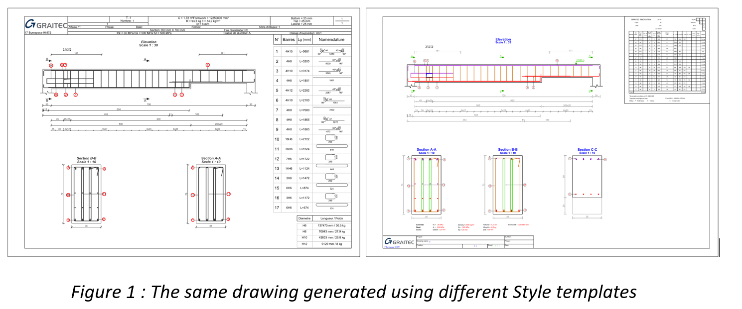
The reinforcement drawings generated by Advance Design modules are highly customizable. The range of possibilities is very large and can be divided into two groups – the current modifications that can be done to the generated drawing and the modifications to the templates used for generating the drawings
Current modifications to the drawing are mainly done graphically or using a series of simple commands available from the properties list. Among these are ability to modify the scale, change the position of views on the sheet, add/remove views (as new sections), rename views, add dimension lines, move descriptions or symbols.
The second group of modifications relates to the templates used for the generation of the drawings. There are many different types of templates available, starting from the most general Drawing Style, which is a template collecting all settings and layouts of views, through templates controlling the settings of colors, lines and symbols used, templates for title blocks and templates for rebar lists.
Today we will look at modifying the general drawing template – the Drawing Style.
Drawing Style – general information
The style template is the most general template and contains a complete description of the drawing, i.e. the orientation of the paper, how many and which views you see, their scale and position on the sheet, used drawing templates, title blocks and bar schedules.
Each module (e.g. RC Beam, RC Forting, …) has its own set of style templates and their number and content is different depending on the regional settings of the program. So drawings may look different according to the default templates for France and the UK for example. However, anyone can easily modify existing templates or add their own.
Changing Drawing Style
Let’s start with how to apply a style other than the default template. The easiest method is to right-click on the first item in the tree (Drawings) and select one of the styles from the available list – Apply Style.

The list shows the styles available in the default styles folder for the given element type and for regional settings (country). By selecting ‘Select styles’ you can preview the contents of the folder and select a file from another location. This command menu also includes a Save Style command that saves all current drawing settings to a new Style template file.
Layout of views
Most of the changes to the settings in the property list (including the sheet format or the type of reinforcement list) as well as the number and type of views are written directly to the template. However, the placement of views and their scale depend on the Layout of views settings. So it is usually not enough to move the contents of a view (for example, a beam cross-section) to a new location on the sheet, but to move its associated rectangular outline, which is presented as a blue frame. Namely, modify the layout of the views on the sheet
To check and modify the layout of the views in the current drawing, right-click and select Edit Layout command.

We will then see the layout of the views, which we can freely arrange on the sheet by moving the corners of the outlines (using grips). This will allow us to ‘anchor’ a given view on the sheet, also in relation to the other views.

By default, the views are generated according to the position of the layout frame as well as their scale is automatically adjusted to its size. But we can change these settings using two options from the view properties.

The ‘Views fit layout’ option is responsible for automatically scaling the view so that it fits optimally in the frame area. If you disable this option, the scale will not be automatically modified when regenerating the drawing.
The ‘Views follow layout’ option is responsible for the location of the view relative to the frame area. If you disable this option, the view will not automatically follow the frame area when the drawing is regenerated, i.e. the last position of the view after it was manually modified will be preserved.

The above description, of course, only briefly introduces the subject of template customization, so I recommend exploring the available options on your own. At the end, one more note – remember that the final effect, i.e. finally generated drawings, can also be saved directly in DWG format, allowing further changes or assembling drawings in CAD if necessary.
Learn more about Advance Design!
- Visit website – https://graitec.com/advance-design/
- Visit Advance Design Virtual Stand – https://graitec.com/advance-design-virtual/
- Linkedin – https://www.linkedin.com/showcase/advance-design-&-advance-design-connection/
- Free trial – https://graitec.com/free-trial/
