Monolithic floor slabs are currently one of the most popular solutions. Depending on the structural system used, they can cover relatively large spans.
In most cases, the slabs are reinforced with a two-way orthogonal grid up and down. A common misconception among designers is that the determination of the cross-sectional area of this reinforcement for the ultimate limit state is based solely on the bending moments which are the same for the directions of the reinforcement. Thus the dimensioning of the reinforcement in direction “x” would be based on the bending moment Myy and the reinforcement “y” on the moment Mxx.
The example of a simple two-span slab, in which one span operates in a decidedly unidirectional manner and the other in a bidirectional manner, shows how to determine the authoritative, dimensioning moments. The loads and geometry are not particularly relevant. We will mainly discuss the nature of the plate work without attaching importance to values. The model and calculations were made with Graitec Advance Design.

It must be remembered that the orthogonal reinforcement grid results from a certain compromise between its optimality from the load-bearing point of view and the ease of subsequent execution on site. In reality the directions of the principal moments can be and in many places are deviated from the direction of the moment Mxx or Myy. Therefore, the most optimal reinforcement would be one designed according to the trajectory and based on the values of the principal moments M1 and M2.
Remember that the values of the principal moments must be interpreted with their directions, since they are not local or global values of the structure. Where the principal directions coincide with the directions of our reinforcement, i.e. x and y, this means that the dimensioning value of the bending moment will be the moments Mxx and Myy and the trajectory of this reinforcement is the best possible.

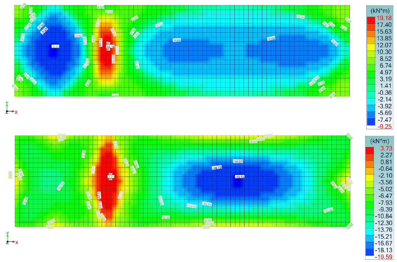
It is easy to see that the directions of the principal moments coincide with the x/y direction in the central bands, but deviate at the corners. Most designers who have ever dimensioned slab reinforcement in more sophisticated FEA-based software have probably noticed that the reinforcement map does not correlate directly with the maps of orthogonal bending moments in the local floor system.


The “butterfly” shape of the two-way free-supporting slab and the top reinforcement of the corners in both the X and Y directions are very characteristic. This is usually the most questionable aspect for designers – after all, the bending moment maps in no way correspond to this distribution of reinforcement – but it is perfectly normal behaviour.
The devil is in the torsional moment Mxy/Myx. Its presence is responsible for the deviation of the moments from the x/y direction. In the main directions we are only talking about the moment M1 and M2, there is of course no torsional moment there. If you decide to deviate from the main trajectory and reinforce the slab with orthogonal mesh, you must take this moment into account in the dimensioning of the reinforcement. The program Advance Design does this automatically of course by determining the relevant dimensioning moment at each grid point. In short, this means the projection of the principal moments onto the reinforcement directions.

Influence of dimensioning forces on the dimensioning of reinforced concrete
When dimensioning reinforced concrete members, the program determines the dimensioning forces which the user can display on the structure at any time.

Literature on the principles of reinforcement design for reinforced concrete slabs recommended the use of bottom diagonal reinforcement in the corners of free-supported slabs with a certain cross-sectional area (most often referred to as maximum span reinforcement in this literature). Designers usually use such reinforcement, but often without being aware of the design necessity. It is important to realize that the above-designed orthogonal X/Y reinforcement taking into account the torsional moment closes the topic and we are not required to use any additional reinforcement with a trajectory separate from the orthogonal reinforcement. The fact remains, however, that orthogonal reinforcement is not fully optimal.
To illustrate this phenomenon, it has been decided to model in the corner a slab whose local directions (and thus also the directions of the reinforcement in the adopted settings) are in accordance with the directions of the principal moments.
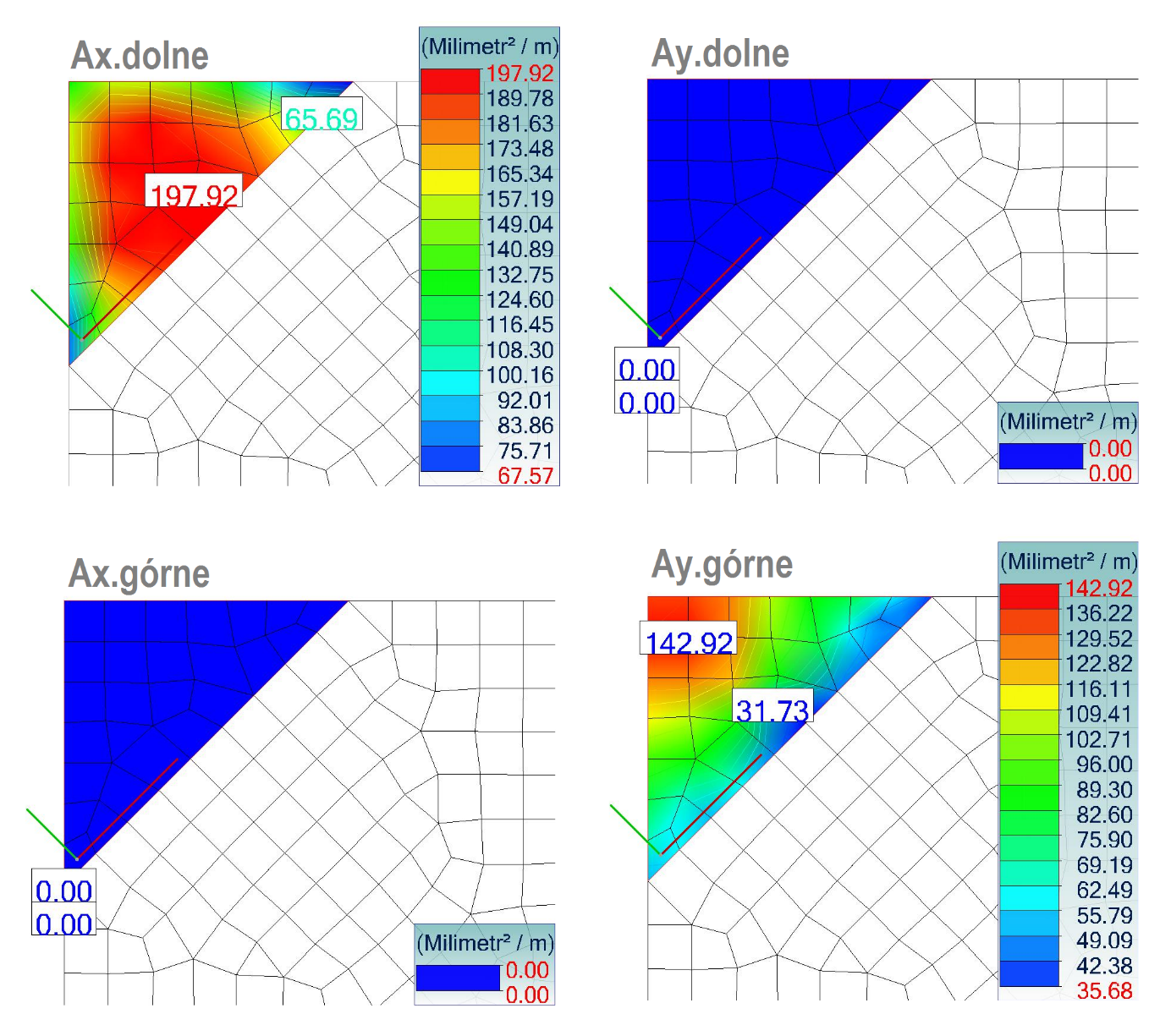
When using orthogonal reinforcement, both top and bottom reinforcement in both X/Y directions were required. For trajectory reinforcement, a bottom reinforcement perpendicular to the bisector and an upper reinforcement parallel to the bisector is sufficient. This means that the principal moments are at this point deviated by 45º from the X/Y direction.

