With the advent of all kinds of computer methods supporting the work of the constructor, we began to design increasingly complex systems, whose work we could previously only estimate using various simplified, tabular methods, supported by analysis and research, but giving little room for manoeuvre in terms of geometry, load patterns, etc. The most popular method for the analysis of building structures is nowadays, and has been for many years, FEM, or Finite Element Method. When designing with such a system we can, to a large extent, model practically any object. This is easy for certain structures, but it should be remembered that the model is only a certain approximation of reality and will behave exactly as we have imposed it.
The FEM method relies on discretisation and takes into account any boundary conditions we ask for. Is the footing really a full restraint as we are used to modelling? Is a reinforced concrete beam really able to transmit the full moment according to the stiffness of the elements to a reinforced concrete wall? After all, it depends to a large extent on the solution of the reinforcement, on the solution of the steel connections, on the nature of the work… What we model for calculations we must try to reproduce as faithfully as possible in the detailed design – or vice versa.
Today, I would like to focus on the issue of stiffness of support elements, above all beams, and why this phenomenon must not be underestimated or whether we can somehow compensate for its lack of consideration. Using this example, I will also introduce the possibilities of Graitec Advance Design, which allows these problems to be dealt with automatically – it has tools for taking into account the actual stiffness in several ways.
Although slab-and-beam systems have somewhat given way to other systems, they are still used – if not fully, at least as a mixed system with another. In plate and column systems, it is sometimes necessary to use edge beams (for stiffening or to deal with shear punching in edge and corner columns) or transfer beams, in slab faults etc.
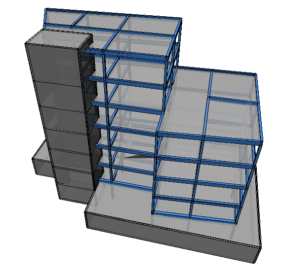
For the purposes of this article, a simple model of a residential building with services on the ground floor, with 6 overground storeys, founded on a foundation slab was prepared. 15cm thick slab in a slab-and-beam system on 25x50cm beams,. The whole structure is stiffened with a reinforced concrete communication shaft. We will consider the first residential storey, i.e., the floor above the ground floor. Loading by own weight, finishing and service category A.
The difficulty in this type of building in terms of modelling is to correctly account for the stiffness of the support members and their interaction with the floor slab. And this has to be taken into account in two ways. On the one hand, it is a modelling issue – the beams are modelled in the axis of the slab, but in reality they are subgrades/tensioners and their stiffness is actually much higher, often 2-3 times. On the other hand, in the case of reinforced concrete structures, for the purposes of statics, we analyse the structure in the elastic state taking into account only the stiffness of the uncracked concrete section. In fact, we should recognise what the stiffness will be with the actual reinforcement and scratching under this reinforcement. And here, exactly, there will be places where the stiffness decreases, but also places where it increases. It may not seem obvious that the beam in the second phase may be stiffer in some places, but there are places where the cross-sectional forces are close to 0, and yet we use there at least structural reinforcement.
I will try to discuss all these issues and how they are solved in Advance Design using the example of the building shown.
Displacements in the first phase of work are shown. It should be remembered that the building is elastically supported, so we cannot interpret these displacements directly as deflections. The whole building settles on the ground, additionally columns experience some deformations. The results are presented for a quasi-steady combination, as for this combination we will consider later the long-term effects in the outlined phase.
For the current model, no action has yet been taken to account in any way for the actual stiffness of the beams, either due to their position (slab uplift) or to the cracking (phase II).
Methods to consider stiffness of beams in FEM
Various methods, more or less faithful but also more or less labour-intensive, are commonly used to consider the stiffness of beams. For some time, designers used a tool built into most FEA programs, the offset – the physical offset of an element from its original position. But it is important to remember how this operation works. The beam is connected to the original nodes by rigid ties, which leads to the element working in a kind of “truss” fashion – the plate is the top chord, the beam offset under the plate is the bottom chord, and the rigid ties are the posts of our mental truss. This results in a reduction of the original moment and the introduction of longitudinal forces according to the principles of work, i.e. the slab begins to be in compression and the beam in tension. It is necessary to include all these forces in the model in some way, but we cannot directly size the beam in bending with tension. Tension would lead to a situation where the reinforcement in the span works both bottom and top, and we know very well from the nature of the beam work that the bottom reinforcement will be important for us in the span zone.
We would need to bring the condition into pure bending, and by using only an offset we are actually reducing the bending moment. We should reduce the forces in our “truss” by considering the action of the integral of the compressive force on the offset arm and include the moment from the effective part of the slab to size the beam. If we were to do this every time, in every beam and every section manually, and then manually size the beam, i.e. use simple calculators with our forces instead of using the forces from our model, we would conclude that using an offset is, in short, silly.
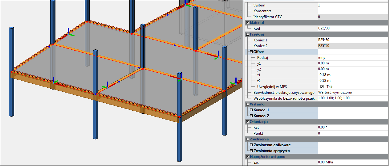
To illustrate this, we will also model the offset in Advance Design. The program has an automatic tool which will perform the whole process of force reduction to pure bending for offset beams for us – this option is called “Rib design” and I will talk about it later. Now, let’s focus on a simple offset and the nature of work of elements using it…something like this can be modelled in any FEA program.
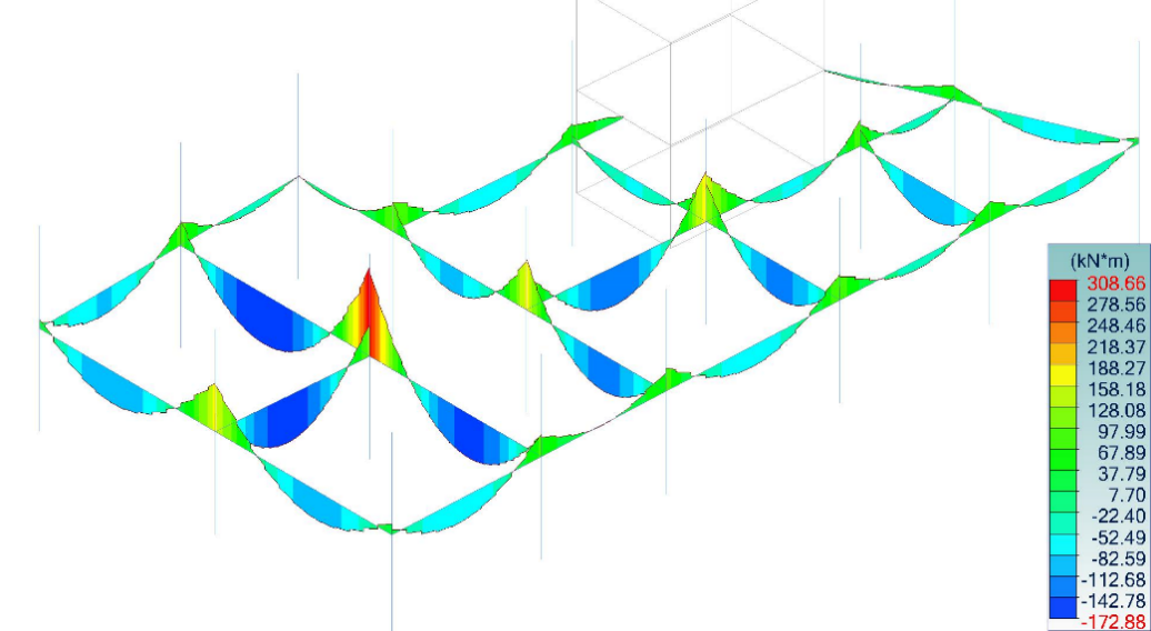
Please note that the moments in the span have decreased from 170kNm to 115kNm. There is also a drastic tensile force of >700kN at these locations. An untrained designer could size the beam for the bending moment alone, which is significantly underestimated, or possibly incorrectly account for the tensile force.
Importantly, this method accurately represents the stiffness of the beams – the floor deflections in this situation are real. The problem is mainly due to the internal forces in the beam as proven.
Note – an offset can be modelled in Advance Design and not included in the FE at the same time. This is important in the age of BIM and exchange of models between different programs. In software for modeling building structures for design documentation purposes such as Revit we model beams in their real geometry. Advance Design will allow us to take into account the position of beams with offset, and it is the designer who decides if, and how, he will take it into account in FEM. This gives a great deal of freedom and goes a step further for designers working with BIM.
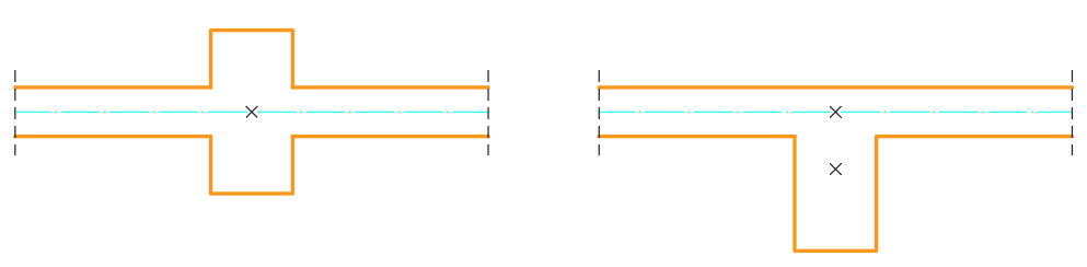
Another popular method, also fully operated by Advance Design, is to artificially increase the section inertia resulting from its actual displacement. The moment of inertia is best determined using Steiner’s Theorem, which in brief makes the moment of inertia dependent on the position of the centre of gravity relative to the axis for which it is calculated. What we want to achieve is easily described by the image below:
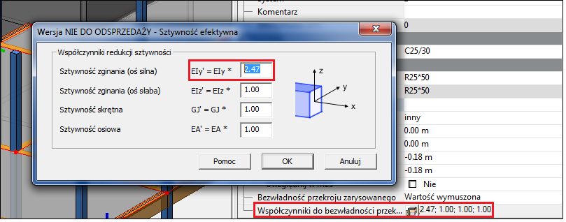
For the beam in the example it is 0.175m – this is also the offset value used above. The moment of inertia of the beam in the axis of the floor is 260416.66cm4, while that of the offset beam is 643429.16cm4. It follows that I need to increase the inertia of the modelled beam by 2.47 times.
In the 2020 version of Advance Design, the designer can define a factor to increase or decrease stiffness for both bending, compression/extension and torsion.
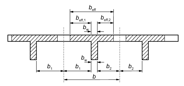
This method is simple, fast and produces correct results. The only thing that is not taken into account is the interaction of the beam with the slab over a certain distance, which the standard defines as the ‘effective width’.
Advance Design Advanced Tools
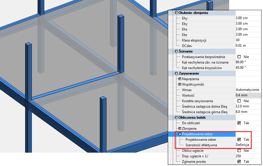
For one of the beams, I have defined the Rib Design option and specified the collaborative width of the slab. Please note its presentation- the beam is defined at the offset, but the slab is drawn into the collaboration. Note that this is an option to dimension a reinforced concrete element, not the FE model itself – the forces to be dimensioned will be determined as I said earlier (reducing longitudinal forces to bending).
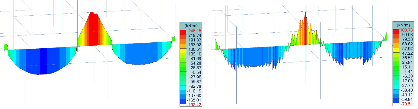
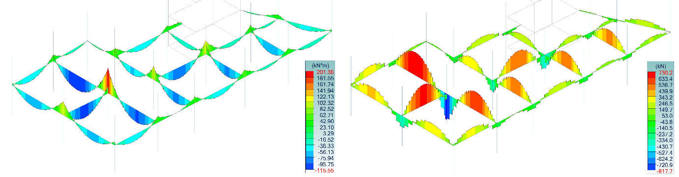
The diagram on the right shows bending moments for a beam with a defined offset – this is very characteristic, the diagram is serrated due to the use of rigid connections in FEM nodes. As you can see, the dimensioning forces for reinforced concrete after the action of the rib design module have a classical shape – the values are correct. You can read more about how this tool works in the document “Advance Design 2016 – What’s new”, as this option has appeared in this version.
NOTE: Advance Design has also determined the stiffness in 2nd phase and the forces for the dimensioning take into account the section cracking. I show the stiffness distribution in the cracked member at the summary of the article below.
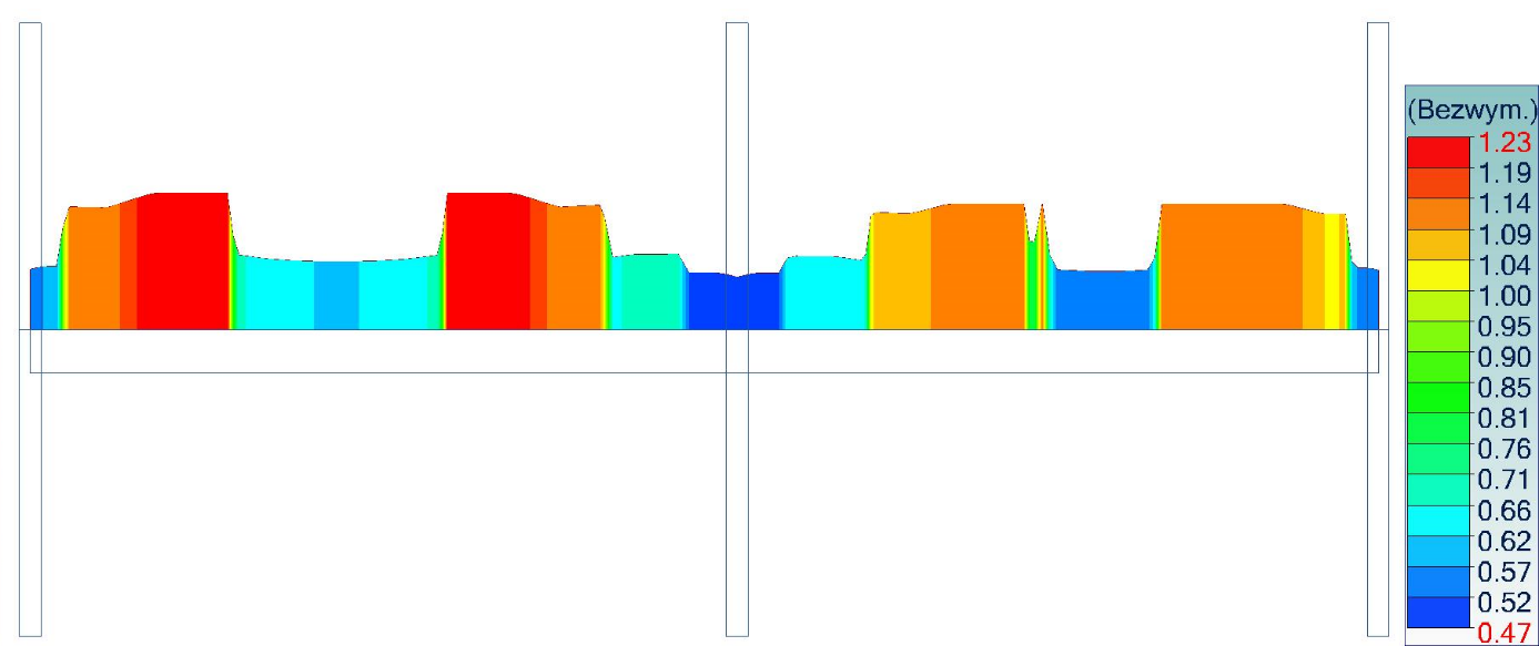
Please note that in the area of the highest moments (i.e. highest cracking) the section loses stiffness by almost 50%. At force levels close to zero, the stiffness increases – because the cross-section is not subjected to cracking and there is nevertheless continuous actual reinforcement.
I will try to talk more about the consideration of stiffness of reinforced concrete elements due to cracking on another occasion – today I tried to focus mainly on aspects of correct FEM modelling.
