Loss of element stability
As well as calculating linear and non-linear statics, Advance Design can also perform what is commonly known as a buckling analysis. Buckling is the loss of stability of an element under axial compression force. As long as this force does not reach a certain critical value, the element will only shorten. Beyond this critical value, the element is thrown out of equilibrium, which is also called buckling. A structure can only be said to be stable if it can return to its original form after being tilted out of equilibrium.
The phenomenon of loss of stability in general is a rather complex issue. The linear buckling analysis itself, however, is quite easy to set up and carry out. It involves solving an eigenproblem that results in eigenvalues and eigenmodes. We will call the eigenvalue the critical multiplier and the eigenmodes simply the stability loss form. The force in an element multiplied by the critical multiplier is the critical force at which the element loses stability.
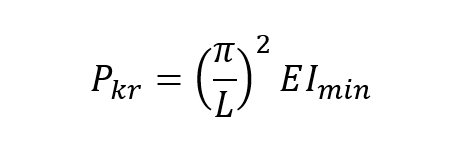
In simple cases (e.g. isolated elements), the critical force may be determined from Euler’s formula:
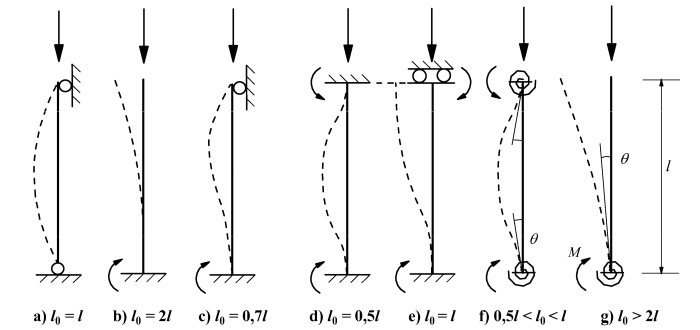
The designer must instead estimate the buckling length of the member, which is sometimes relatively easy. The forms of loss of stability and the buckling length for simple static schemes are generally known and are presented, for example, in EN 1992-1-1.
The problem starts to arise with unusually braced structures, where it is not so easy to estimate the rotational stiffness of the nodes. By solving a linear buckling analysis, it is possible to know the critical force and thus the buckling length.
Linear buckling analysis
The buckling analysis gives an answer to how close an element/structure is to losing its equilibrium state. If the critical factor is less than 1 (i.e. the load would have to be less than that currently occurring) the structure can practically be excluded from further calculations. The value of this multiplier if it is greater than 1 will give us information how sensitive the structure may be to second order effects and imperfections. This is mentioned in clause 5.2.1(3) of EN 1993-1-1, where it allows the use of 1st order analysis in calculations, provided that αcr > 10.
For a simple example of a cantilevered steel column (IPE400) 8.00m high loaded with a unit axial force, the results of the buckling analysis are presented below.
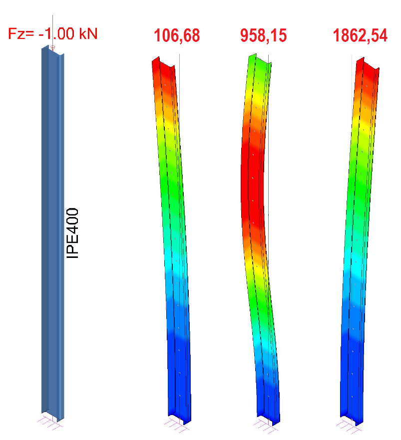
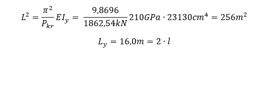
The first two forms of buckling are in the direction of the weaker axis of the section, the third in the stronger axis. The smallest critical factor is 106.68, assuming that the force was unit. That is, if the axial force was 106.68kN the column would buckle. Looking at the form of the loss of stability in each plane it is easy to see that the buckling length is 2*L – you can also ask the software for this figure – for evidence it will be determined using Euler’s formula.
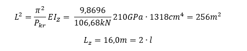
An analogous check can be made in the second plane, the lowest coefficient of which corresponds to the third form of loss of stability. For a classic cantilever in both planes, 16.0m is expected in this case.
As you can see, buckling analysis is easy to carry out and accurate in simple cases. The case shown is as simple as possible, where the bar is subjected to axial, ideal compression.
The important thing to remember is that simple buckling analysis is fully linear – that is, both geometrically and material-wise. It is a very fast tool giving an answer in a short time about the potential behaviour of the structure, but it does not take into account 2nd order effects, and the material works elastically throughout.
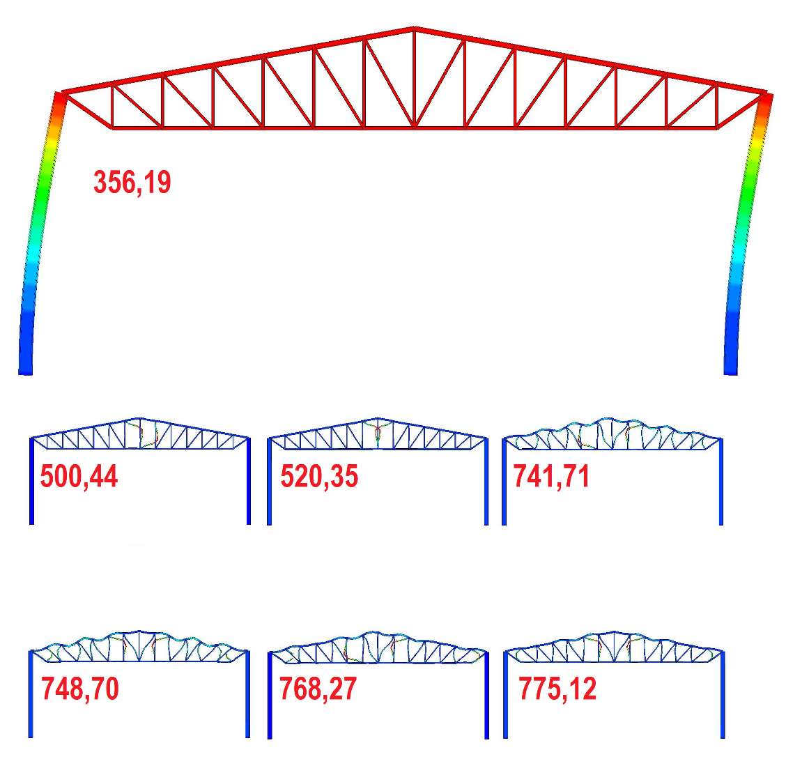
In a situation where the whole structural system is analysed, and not just a separate element, the matter is somewhat more complicated – the critical factor, closely related to the form of loss of stability, should be identified with the elements that lose stability in this form. For a simple frame, analysed only in the plane of the system, 20 successive forms of loss of stability were obtained. The axial forces are shown below (only in members that are in compression, assuming that they do not lose stability in tension).
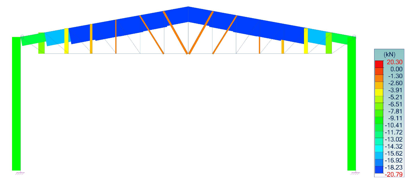
As shown in the image below, the 1st form of loss of stability is a global, canted form. The frame columns clearly lose stability in this form – the critical multiplier is 356.19, so with an axial force of 10.16kN, the critical force is 3618.89kN. Each subsequent form is responsible for the loss of stability of the compressed upper chord and the compressed posts and diagonals of the truss. The multiplication factors of these forms cannot, of course, be taken into account for the determination of the critical force and buckling length of the columns for example. Members that were not in compression in the buckling case do not lose stability.