As the 2022 version of GRAITEC Advance Design introduced the Crane Moving Loads feature, in this short article we will take a look at the moving loads available in Advance Design – the Traffic load and the new Crane load. As the traffic load generator has been available for a long time, I will present only brief information about it and focus mainly on crane loads.

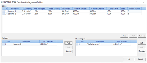
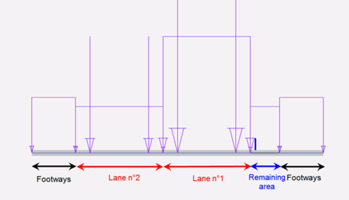
Let us start with the traffic load. The traffic load generator enables us to create traffic loads on road bridges according to EN1991-2 (Section 4). In order to create the appropriate traffic loads on the road bridge (on planar elements), we define graphically the elements composing the carriageway: one or several traffic lanes, remaining areas and footways or cycle-tracks.

The next step is to add a Traffic loads family and select the appropriate load model, according to the provisions of the Eurocode. Five load groups are available, containing respectively:
- gr1a – combination of the concentrated loads (Tandem Systems) and the Uniformly Distributed Load (UDL System) with the uniformly distributed load on footways.
- gr1b – a couple of concentrated loads that represent a single axle of a truck, for creating concentrated forces along the lane.
- gr2 – combination of the concentrated loads (Tandem Systems) and the Uniformly Distributed Load (UDL System) with braking and acceleration forces and centrifugal forces.
- gr3 – uniformly distributed load on footways.
- gr4 – uniformly distributed load on footways and traffic panels.

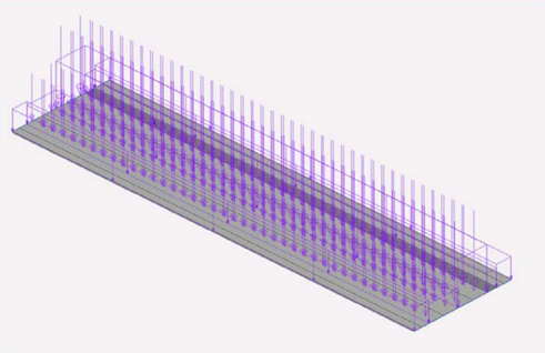
After automatically assigning the load parameters to the roadway, we are ready for load generation in the model.
Depending on the load model selected, this results in load cases that include uniform loads as well as a series of consecutive steps in the position of the concentrated forces from the vehicle wheels.
For loads from cranes, the process is somewhat similar. The first stage consists in defining graphically the route of the crane forces – it can be a single polyline to model the forces moving along a single rail (for monorail crane modelling) or two parallel lines to model the route for the forces from two trucks on both sides of the bridge crane.

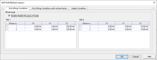
The next step is to add a Crane object. It is used to describe the geometry, such as the number and spacing of the wheels, and to describe the forces from the wheels.

In the simplest case, the forces on each wheel can be defined manually, separately for each wheel. But it is also possible to use three different automatic methods, so that the wheel forces are automatically determined according to the rules of the standard.

We have three methods available for the automatic determination of forces:
- By crane loads (EN 1991-3) – for defining wheel loads automatically on the basis of entered crane loads, by using Eurocode EN 1991-3 rules. In this method several loads of different origin (e.g. loads from crane self-weight, from the weight of the load, from braking forces, etc.) are separately entered for each wheel. These load components are combined with the dynamic factors and the final wheel forces are determined. As the result this method gives several groups of load sets (ULS Group 1 to 6), according to the EN 1991-3.
- By crane parameters (EN 1991-3) – for defining wheel load automatically on the basis of entered crane parameters, by using the Eurocode EN 1991-3 rules. The main difference compared to the previous method is that the values for each wheel are not entered, but the crane parameters (like self-weight of the bridge, self-weight of the trolley and the crane capacity) are given. The output is the same as for the previous method – six groups with sets of forces for each wheel.
- By crane parameters (ASCE/NBCC) – similar to the previous one, so we do not enter the forces on individual wheels, but such loads are calculated automatically on the basis of entered crane parameters. But this time the method of automatic load generation is based on the general method, related to US/CAN standards (especially ASCE). But it is worth to mention, that the load generation rules are generic and are essentially independent of any standard.
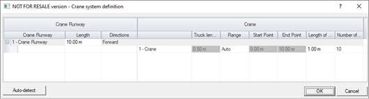
With the crane runway and the crane with the forces on the wheel, we can proceed to the next step, which is the definition of the load family. Here we determine the range of crane movement and the number/length of moving load steps.
The generation of crane moving cases is done automatically after using a ‘Generate’ command available when right click on the Crane Load case family. After it is run a set of moving load cases are generated, separately for each crane and each step position. They contain the forces from all wheels in a given position. Depending on the definition of the crane, these are both vertical forces and horizontal transverse or longitudinal (from braking) forces.

Together with the load case generation, sets of force envelopes from all force positions are also generated.
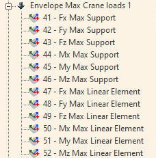
Importantly, we can define more than one crane and place them on the same or different runways. In this case, the program will generate for each crane a series of all force positions and then, when the envelope is generated, only the possible combinations of crane positions are considered.

The final load combinations are defied by using typical load cases (dead, live, wind…) and Crane Envelopes. This is particularly important when there are a large number of crane steps and especially many cranes, as the final combinations consider only a dozen or so envelopes instead of thousands of crane position combinations.
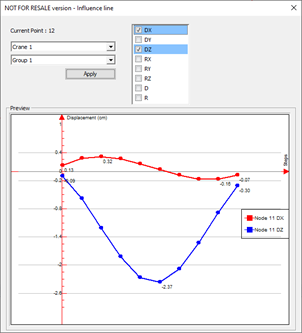
The static calculation and the results for the combination cases do not differ from other load types and you can check the results for each crane position as well as for the envelope of the crane forces. Specific to crane is a new type of graphical output – the influence line diagram. It shows graphically the value of the result at a given point for all successive positions of the crane. Although in this version of the program the influence line diagram can only be displayed for displacements in structure nodes, it is one of the additional tools useful when analyzing the results.