All modern design applications require a solid testing mechanism in order to detect any regression regarding the quality of the results but also to cover all areas of the application (GUI, CAD, correct workflows, …).
Advance Design has a mechanism based on a script that works like a batch session. This mechanism was mainly designed as a system for automatic tests to offer access to almost all areas in the application. In this way we can reproduce various scenarios.
Since it’s quite extensive and very cryptic, the main idea to use this mechanism is to start from a base script and adjusted or completed with the other commands. A base script can be generated by Advance Design. Usually an automatic test in our QA system consist in a model and a script. Both are passed to Advance Design in command line and the application executes the script.
In the following points we will go into details for such scenarios.
- The base model creation
The first step consists in creating a model using your preferred localization and norms. The creation of load cases and their configuration is also recommended.

The analysis hypothesis, options for concrete analysis, steel analysis, etc. can also be configured at this step. Then, after saving the model, a back-up is recommended because it will be needed at a later step.
Until now we could say we have a complete environment. From this point we can start generating the structure elements (linear elements, planar elements, footings….).
2. The elements creation through scripting
2.1. Commands syntax and script composition
The syntax of a command that creates an element with geometry is composed by:
the_name_of_the_command+space+(x_coordinate;y_coordinate;z_coordinate)[and repeat the ’+ space+(x_coordinate;y_coordinate;z_coordinate)’ for all the points in geometry]
’.’ is the coordinate decimal separator, and ‘enter’ is the separator between different commands, so each command is on a different line in a script.
A script contains multiples commands and the last command has to be ’end_auto_script‘.
You can generate a list of commands as bellow in Excel with macros, Dynamo or with another familiar program or tool.
E.G.:
punctual_rigid_support (5.0000;0.0000;0.0000)
punctual_rigid_support (15.0000;0.0000;0.0000)
punctual_rigid_support (15.0000;10.0000;0.0000)
punctual_rigid_support (5.0000;10.0000;0.0000)
linear_element (5.0000;0.0000;0.0000) (5.0000;0.0000;5.0000)
linear_element (15.0000;0.0000;0.0000) (15.0000;0.0000;5.0000)
linear_element (15.0000;10.0000;0.0000) (15.0000;10.0000;5.0000)
linear_element (5.0000;10.0000;0.0000) (5.0000;10.0000;5.0000)
surface_element (5.0000;0.0000;5.0000) (15.0000;0.0000;5.0000) (15.0000;10.0000;5.0000) (5.0000;10.0000;5.0000)
windwall (5.0000;0.0000;5.0000) (15.0000;0.0000;5.0000) (15.0000;10.0000;5.0000) (5.0000;10.0000;5.0000)
windwall (5.0000;0.0000;0.0000) (5.0000;0.0000;5.0000) (5.0000;10.0000;5.0000) (5.0000;10.0000;0.0000)
windwall (5.0000;0.0000;0.0000) (5.0000;0.0000;5.0000) (15.0000;0.0000;5.0000) (15.0000;0.0000;0.0000)
windwall (15.0000;0.0000;5.0000) (15.0000;0.0000;0.0000) (15.0000;10.0000;0.0000) (15.0000;10.0000;5.0000)
windwall (15.0000;10.0000;0.0000) (15.0000;10.0000;5.0000) (5.0000;10.0000;5.0000) (5.0000;10.0000;0.0000)
end_auto_script
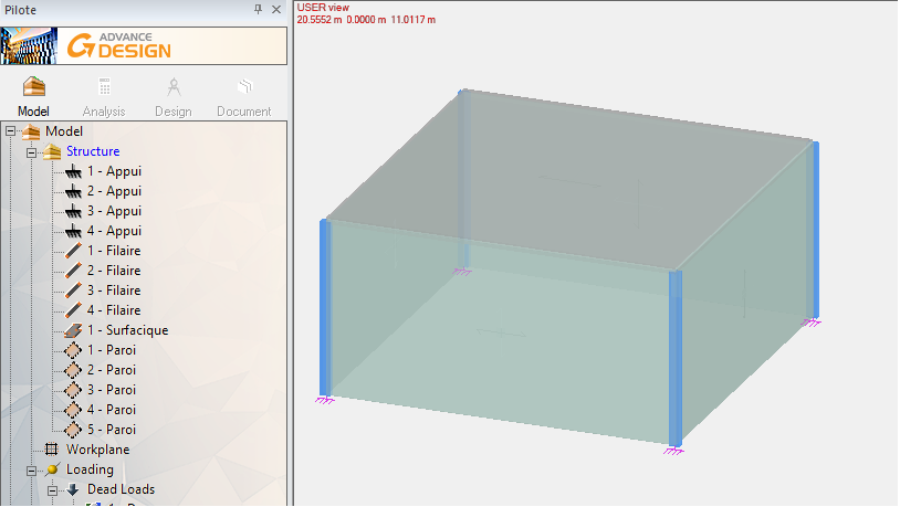
This script will generate the elements in the model like in the picture bellow:
In order to create elements using commands as the ones above, when running one of them or the script the following snap modes have to be disabled: extension, tracking, ortho, relative and length on element.
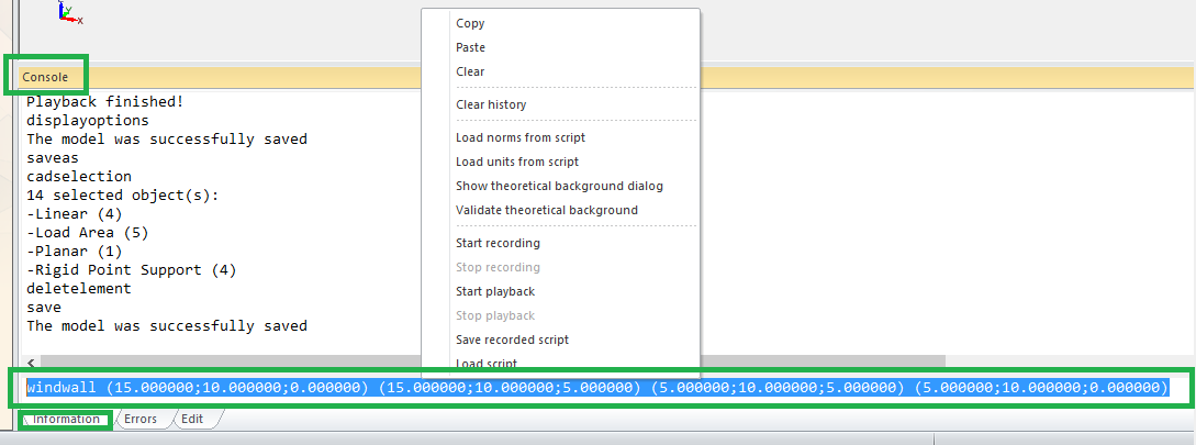
All the commands executed by the user are recorded in the history of the console which is accessible in the input console line (E.G.: selecting an element, calling a ribbon or menu command like creating an element, etc. …).
For checking any executed command syntax, scrolling through the commands history is possible by clicking the input console and pressing left arrow key for each command (using right arrow will walk you back to the last executed command, opposite to the left arrow key, but only after starting to use left arrow). To copy it the recommended way is by selecting the text with the mouse, right clicking it and selecting copy from the contextual menu.
2.2. Script saving, recording and playing
If the script is generated with Excel/Dynamo/etc. then make sure the generated file has the extension set as .ads.
For manual script creation a text file with ads extension is needed. It can be created with Notepad or any other text file editor. After the creation of file copy the script described above at point 2.A. in the empty file and save it as your_script_file_name.ads .
For script recording in AD, right clicking in the input line of the console and choosing ‘start recording’ from the contextual menu starts the recording. After the user interaction with the program (E.G.: selecting an element, calling a ribbon or menu command like creating an element, modifying options in a dialog, etc…), right clicking in the input line of the console and choosing ‘stop recording’ a dialog is launched for choosing the name and the location of the script. There are some limitations that are listed at the end of the document.
To play the script for scenario 2.1, right click in the input line of the console and choosing ‘Load script’ from the contextual menu starts a dialog to choose the script file. After choosing it AD start playing the commands from the script one by one with a delay between them. The user should not move the mouse or press any key while playback is in progress. At the end a message will be printed in the console that notifies the end of the operation.
3. Model calculation and reports generation
At this step start recording a new script as described above. The automatic wind, snow, traffic loads, etc… and combination must be generated if needed. Then the analysis model should be created, maybe also the concrete analysis, steel analysis, etc…. Then in the report generation dialog add the needed reports and optionally change the report type: (Doc, docx, xls, xlsx(for the these first 4 extensions Office suite is required), rtf, txt). In the gif sample, the selected type is xls but in the script rtf type is selected in case Office is not installed. The report is generated in the document folder of the model and it is not automatically opened.
In the end you need to stop the recording. The resulting script can be used as a template script and should be modified/adapted to include the creating elements commands (from the point 2.1.). They should be added right after the last set_unit command:

4. Running the script in batch mode.
At this step you should use a copy of the backup model from the 1st point. Running a batch mode can be achieved by running a bat in which the command is having the following syntax:
“X:\Path to AD\Bin\AdvanceDesign.exe” /s “Y:\path to script\script name.ads” /m “Z:\path to model\model name.fto”
E.G.:
“C:\Program Files\Graitec\Advance Design\2021\Bin\AdvanceDesign.exe” /s “d:\AutoTests\models for new tests\newtest\combined script.ads” /m “d:\AutoTests\models for new tests\newtest\FTDoc15.fto”
A bat file can be created in Notepad and saved as ‘file_name.bat’ when selecting all types as the extension in the save as dialog.
5. Scripting recording and playback limitations
- Double-click in pilot; instead, used right click or other commands
- Combos in toolbars.
- The Data Grid dialog (different technology, in work).
- Buttons that open dialogs in Property list and the recording of the GUI operations in that dialogs.
- Changing properties in property list commands might have to be updated at each version/subversion of AD because the commands are depending on the identifiers of the properties which are changed almost each version.
- Changing the sections and materials for elements from property list.
- Changing height for level in Property list
- Copy/move dialogs.
- Double-click on result curves in order to save them as *.jpg
- Only basic modifications in tables are supported
- The measurement units must be the same as the ones installed by the kit
- When creating a circle, the radius will be specified in console, not by clicking on the screen.
- Modifications of snapping are to be done using the toolbar/ribbon.
- Creating loads on selection.
- All needed section cuts will be created before starting to register the script.
- Mesh preview for planar elements.
- Selecting the work plane.
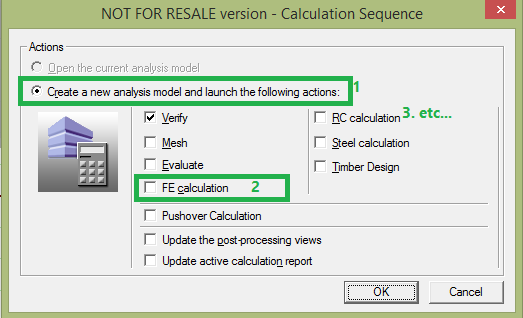
- When creating the analysis model, the script should compute a new analysis. When automatically running, if an analysis was computed for the current model, the check boxes for analysis types are disabled, therefore the test will try to open an existent analysis (which does not exist since we should run on a clean model). Therefore, when registering the script, even if the model is a new one and the option to create a new analysis is already selected, select “Create new analysis” and then the analysis type(s).
- Do not use right click in reports window. Use instead left click and the existing buttons.
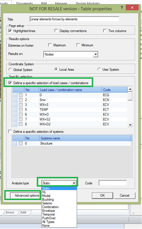
- In order to change the cases/combinations for the report, do not use the Cases/Combinations window. Instead, use the Report properties window (select report and click Properties button) select advanced options to expand the dialog and check the specific case/combination and use the analysis type combo from the below of the extended window:
When adding more family cases or loads, do not use the keyboard to insert the number. Use instead the arrow buttons.

- The two slides for size from the display options window (Alt+x): or from the ribbon
- The window for pressure generation.
6. The power of automation
This tool is very efficient for our QA system but can be very useful also for anyone who wants to automatize repetitive scenarios but also to feed Advance Design with entire building structures extracted from another application. Just do the scenario inside the application, save the script, adapt it if you need it and run it.
