During the last few years, the Advance Design reinforced concrete modules have been progressively getting more and more configurable for automatically generated reinforcement. New customer-specific settings are added in each version, making the modules for RC beams, RC columns, RC foundations as well as RC walls and RC slabs more and more configurable. This allows you to set the parameters in such a way that the reinforcement for the elements is generated according to your expectations. And of course the expectations on the reinforcement of an element can be different, depending on the user and sometimes on current needs. Sometimes in one project the focus is on the optimum use of the reinforcement and in another on the ease and speed of construction.
Today, let’s look at a few selected reinforcement settings for reinforced concrete beams.
Common longitudinal reinforcement for the spans
Imagine that we have a reinforced concrete beam with several spans. We have modeled and calculated it as a continuous beam, and we want to generate the longitudinal reinforcement for each span separately. This is the default setting of the module.
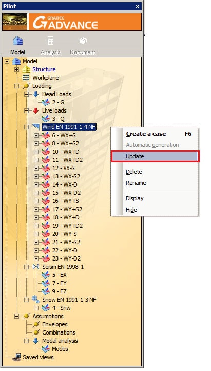
But if we want to get the effect of continuous longitudinal reinforcement on all spans we can get it very simply. In the window Reinforcement Assumption on the Longitudinal Bars tab we have dedicated options ‘Bars on Multiple Spans’.
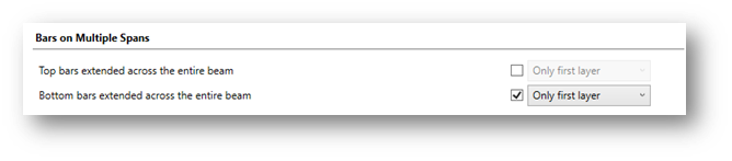
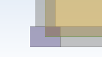
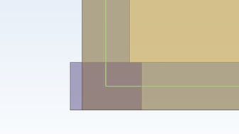
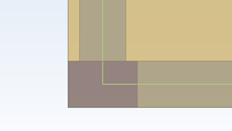
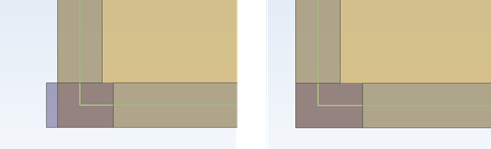
The option Top/Bottom bars extend across the entire beam can be enabled independently for longitudinal bottom and top reinforcement. Additionally, you can select whether you want to extend bars from the first layer only or also bars from all layers (if any).
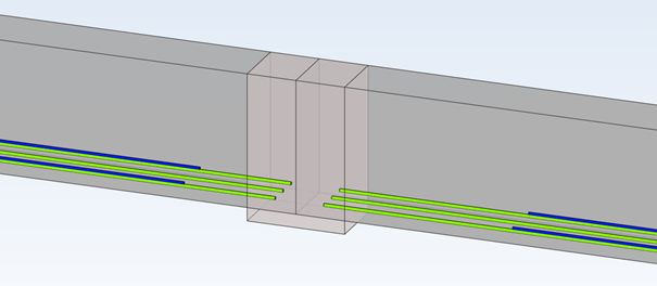
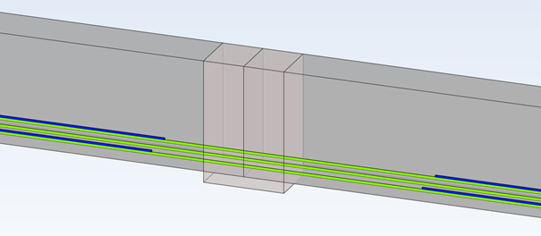
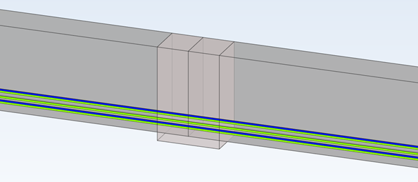
Let’s take a look at the examples in the pictures below (only the main bars of the bottom reinforcement are shown for easier understanding).
Linking of longitudinal members with transverse reinforcement
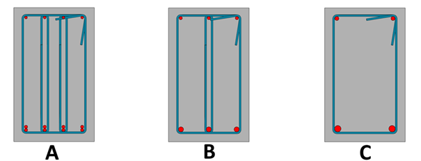
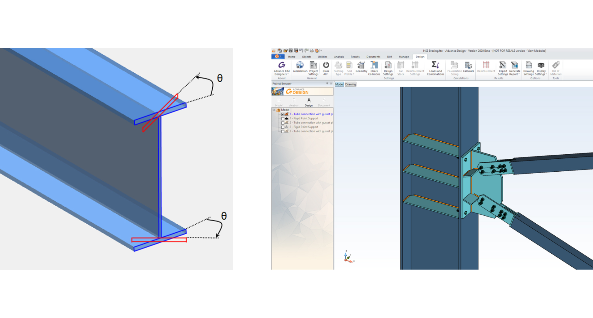
One of the settings for transverse reinforcement is the default shape type of these bars. In the Reinforcement Assumptions window on the Transversal Bars tab, we have a number of useful options for setting shapes. One of them is the possibility of deactivating the automatic selection of shape types and the possibility to choose from the list the type of transversal reinforcement – and actually the way of joining the longitudinal bars not located in the cross-section corners. We have 4 types available, as on the pictures below: A – None, B – Stirrups, C – Pins and D – Multiple links.
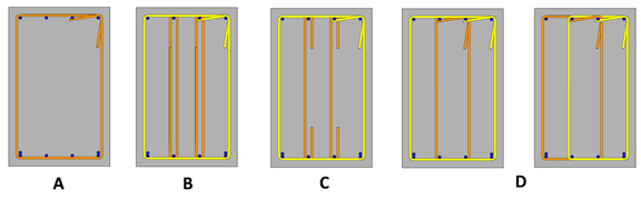
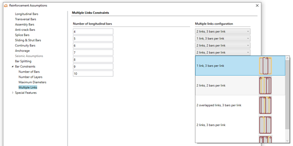
Note that multiple links for this case can have two solutions: with one large and one small stirrup or two identical ones. When we can have more longitudinal bars in a layer (than 4, as is the case on the above picture), the number of possible configurations for multiple links is larger. This can also be set according to our needs in the Multiple Links tab where we can graphically choose default settings for different number of longitudinal bars.
Maximum number of longitudinal bars
One of the reinforcement settings is the number of members of the longitudinal reinforcement to be generated due to the width of the beam cross-section.
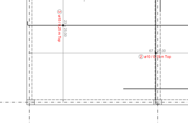
These settings are available in the Reinforcement Assumption window on the Numbers of bars tab. We can set there the number of longitudinal bars in the span and in the support for different width ranges of the cross-section.
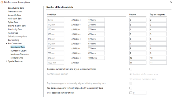
So for example if the cross-section is 300 mm wide, 4 longitudinal bars (in the span and in the support) are taken automatically. Depending on the required calculated theoretical reinforcement, the program will then select the diameters of these bars and if necessary, add additional layers of bars.
But among the options available in this configuration window we can also find a special option that changes the way of determining the number of longitudinal bars. It is called Consider number of bars and layers as maximum limits. When this option is not active, the entered number of bars is considered as imposed. When this option is active, then the number of bars is considered as maximum allowed value and the number of bars will be automatically determined based on required reinforcement area.
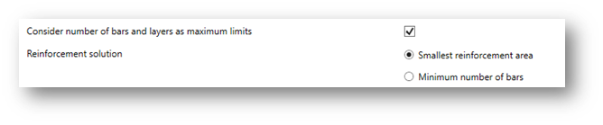
As the selection of this method for a given required reinforcement area can lead to a variety of possible solutions, e.g. fewer members with larger diameter or more members with smaller diameter, two options are additionally available for choosing the preferred solution:
- Smallest reinforcement area – will assure the smallest difference between the real and the theoretical reinforcement area.
- Minimum number of bars – will assure the minimum number of longitudinal bars and will eventually lead to bigger diameters.
Typically, both options produce fewer bars than the fixed number of columns method, especially when the second option is chosen, but the end result also depends heavily on other assumptions. We can see a simple example for a cross section having 300 mm with three different settings used: A – the number of columns of bars is fixed (which gives 4 columns of bars for this width), B – the number of columns of bars is a maximum limit, and the first option “Smallest reinforcement area” is selected, C – as previously but the second option “Minimum number of bars” is selected.
All these settings give different configurations for the number and diameters of longitudinal members, but they all satisfy the section verification requirements and give a larger area of real reinforcement than the required area of theoretical reinforcement.
The above settings are only a fragment of the possible settings. It’s worth to get to know all the settings, because thanks to the multitude of configuration options and the possibility to save them to templates, using design modules of Advance Design we can dramatically accelerate the daily work.
Article by Mateusz Budzinski / Technical Product Manager / GRAITEC


 Advance Design 2015 now features the NTC 2008 Italian codes for:
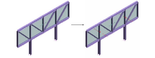
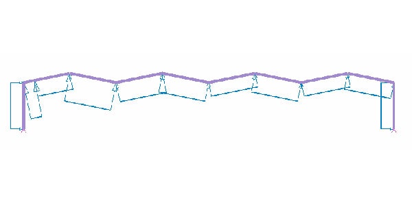
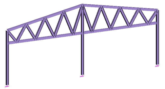
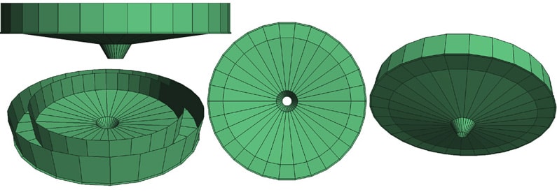
 On a continuous growing market in the emerging countries that invest more and more in their infrastructure, the use of tapered elements for steel structures increased, especially for portal frames having large spans. However, without dedicated tools to complete large and complex steel projects, the design process can take longer. Advance Steel 2014 provides valuable assistance to all designers with a very comprehensive set of features: a new object, “tapered beam”, which allows the user to define elements having a variable cross section, including the possibility to combine different constraints on each segment (fixed or variable lengths, parallel flanges or not, etc.).

 Two of the key features of Advance Concrete (Multi File data storage and multi CAD platform) have been at the heart of version 2014. Performance and robustness have been brought in these two areas: the time to create new views and updating of existing views, has been largely optimized. More improvements in performance, which are very significant, are available: faster reinforcement elements renumbering in complex cases faster “3D Copy” feature which allows the users to copy the 3D reinforcement of an element in all corresponding views with its identification, symbols and associated dimension lines. Lastly, required corrections were made in Advance Concrete, with the target to deliver more stability and significantly higher robustness for Advance Concrete 2014.
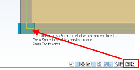
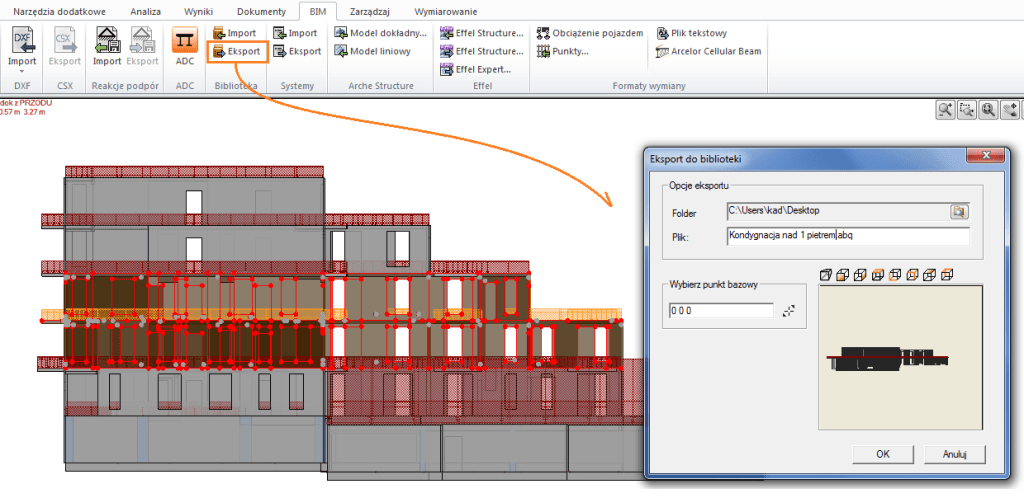
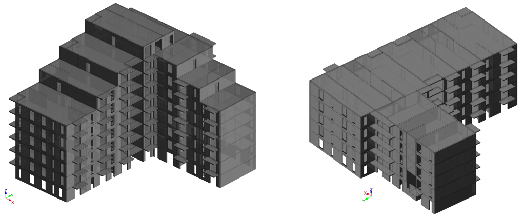
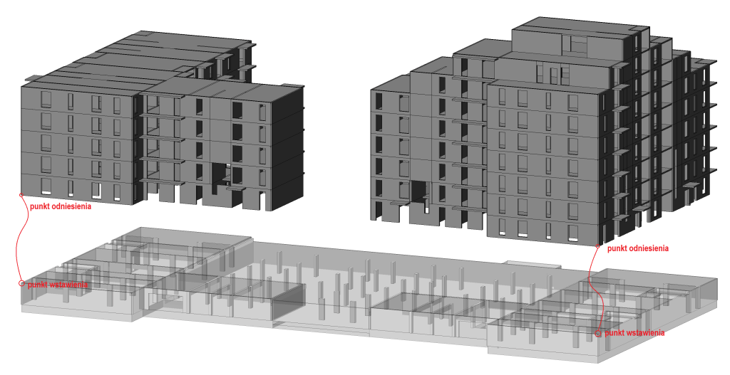
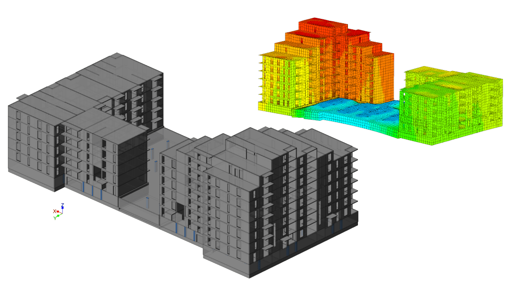
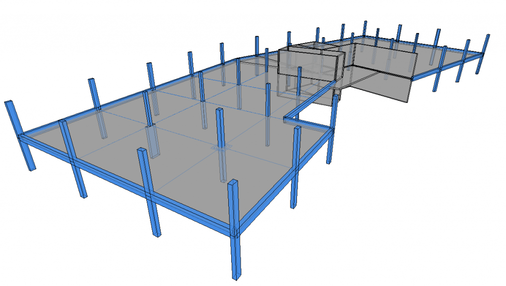
 In a context where all structural designers are increasingly receptive to the BIM concept and its associated gains in terms of productivity and safety, Advance Design 2014 provides a set of new features designed to facilitate the BIM exchange in the design offices structure or between the architects and the design offices. The model which is used for structural simulation by the engineer can be a variation of the geometrical model produced by the architect which, in the end, can be significantly different: the elements are coplanar, intersecting axes, the elements extremities which are to closed are merged, small details of the facade are not modeled, etc.


