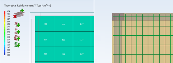
With version 2022 of Advance Design, a module for the generation of the real reinforcement for concrete slabs has been introduced. One of the main tasks of this module is to prepare the reinforcement cage on the basis of the previously calculated theoretical reinforcement and then to prepare a drawing with the description of this reinforcement.
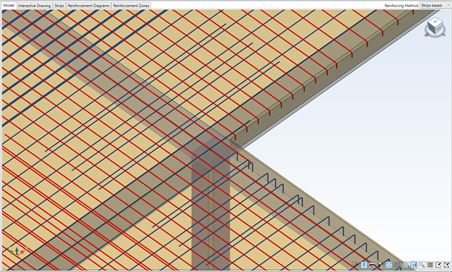
In practice, the theoretical reinforcement is calculated on the basis of the results of the FEM (finite element) model. However, the FEM calculation model itself, by its nature, is usually a simplification of the real geometry of the structure.
But for the real reinforcement and the drawing documentation we have to take into account the real geometry of slabs and supporting elements like beams, columns and walls. Of course, the extent to which the calculated and real models diverge depends on how the FEM model was created. So, how can we ensure that the real reinforcement and the drawings correct in case of model differences? Let’s take a closer look at the possibilities the new module for reinforced concrete slabs in Advance Design offers in this respect.
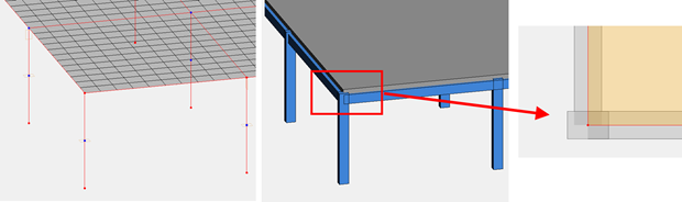
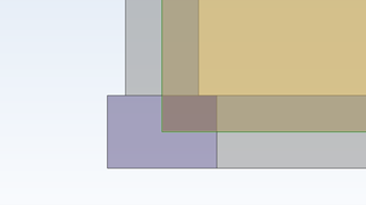
Consider the first case – the position of the axes of the supporting elements (beams, columns and walls) in the FEM model is consistent with their real position, while the outline of the slab is simplified – the edges of the slab are modelled along the outline of the support axis. This is a common case, especially when the model has been created based on construction axes.
After importing the slab model into the RC design slab module we’ll see the outlines of the supporting elements and the edges of the analytical slab model (green lines in the images below). While the analytical model cannot be modified at this point, we can automatically modify the external geometric contour of the slab.
In this case, we can automatically adjust the geometric contour of the slab using the option available in the geometry parameters window called ‘Slab physical contour’.
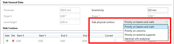
With this option we can decide whether:
->leave the geometric contour unchanged, as identical to the analytical contour;
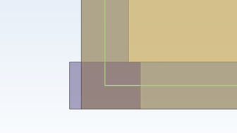
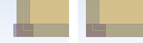
-> extend the geometric contour to the outer contours of beams and walls;
-> extend the geometric contour to the outer contours of the columns;
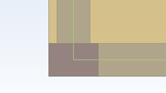
-> extend the geometric contour to the outer contours of any supports (beams, walls and columns). For this corner example, the effect of this last option is the same as for the previous one.
Note that the change concerns the geometric contour of the plate, while the analytical contour remains unchanged. Therefore the values of the determined theoretical reinforcement do not change and the generated real reinforcement in the stretched area of the slab is assumed to be the same as on the edge of the analytical contour.
Let us now consider a different case – the position of the support elements in the FEM model is different from the real one. To illustrate this we will use the same corner from the model shown above. Let us therefore assume that in reality the column is aligned with the correctly modelled beams.
In this case we can use a graphical method to edit the geometric model. To do this, we select the appropriate icon and choose graphically the element that we want to modify.
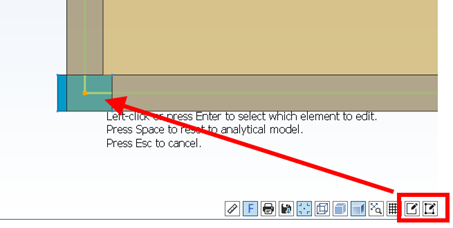
The new position of the axis is then indicated graphically or the value of the displacement vector is entered from the keyboard.
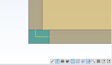
In a similar way, we can move beams and walls. In addition, it is also possible to graphically modify the position of individual edges of the geometric model of the slab.
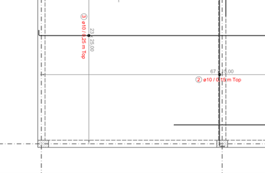
Of course, when the geometrical contour of the slab is changed, this affects the arrangement of the reinforcement bars, including their number and length. On the other hand, when the position of the supports is modified, in most cases only the reinforcement drawing is influenced.
Thanks to these easy-to-use methods of geometry modification, the final effect, i.e. automatically generated drawing, corresponds with the real geometry of the slab.