Product technical specialist
Abstract
In this article, we will compute the shelter factor that applies to a free-standing wall to account for the presence of an upwind wall or fence.
Keywords: Advance Design, wall, free-standing wall, Eurocode 1, EN1991-1-4, return corner
1.Introduction
In a previous publication, we have covered the determination of wind forces on a free-standing wall at the Eurocode 1:
The present article goes one step further by considering the interaction between several walls, and the sheltering effect they may produce on each other.
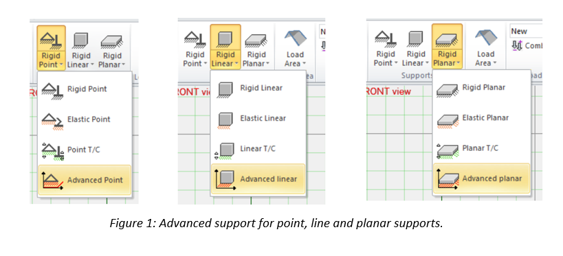
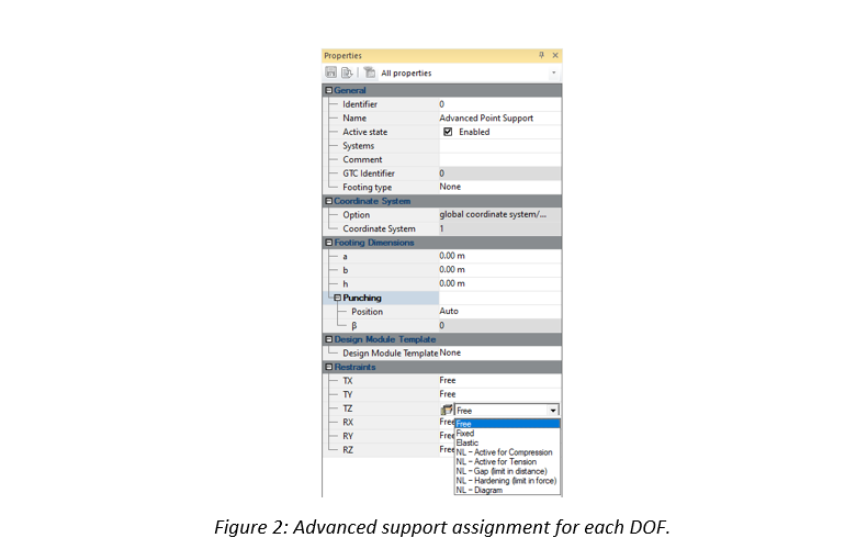
In addition to these supports, a user defined nonlinear support mechanism is also possible (“NL-Diagram” option in Figure 2).
2. Theory
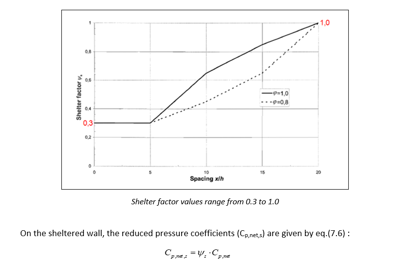
Shelter factor is defined in §7.4.2 from EN1991-1-4.

This coefficient will reduce the pressure coefficients when an upwind wall is able to provide protection to the wall under consideration.

The shelter factor can be determined on Figure 7.20, based on:
- The spacing between the two walls (x)
- The solidity ratio of the sheltering wall (φ)
- The height of the sheltered wall (h)
3. Example
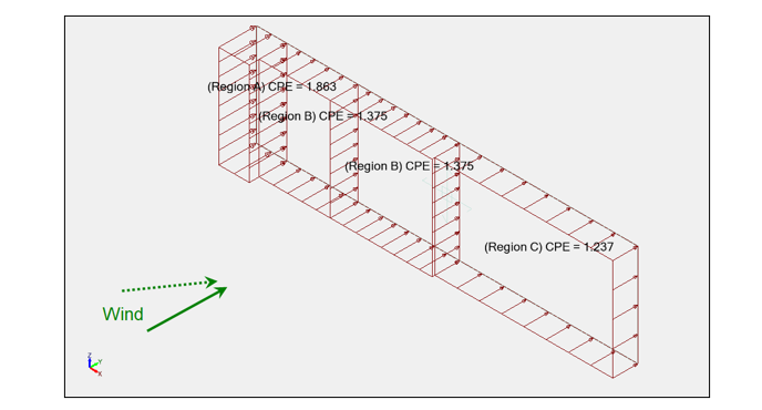
Assume a 15m x 4m wall, with a φ = 0,9 solidity ratio.

The pressure coefficients on this isolated wall would be:
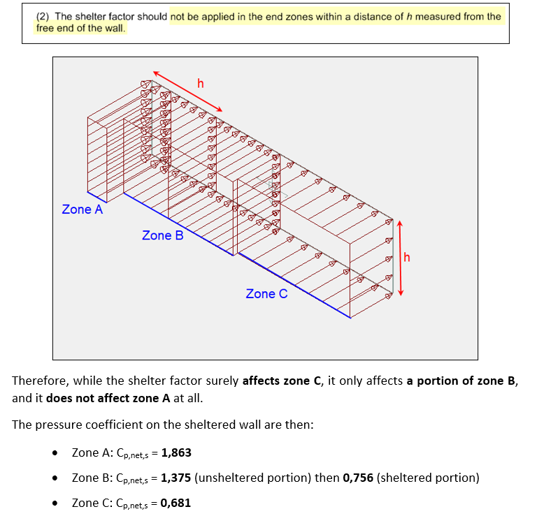
- Zone A: Cp,net = 1,863
- Zone B: Cp,net = 1,375
- Zone C: Cp,net = 1,237
Now, if a similar wall, were to be located at a 40m distance, it would produce a sheltering effect that would be introduced in the calculation through the shelter factor.


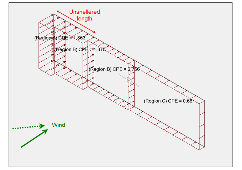
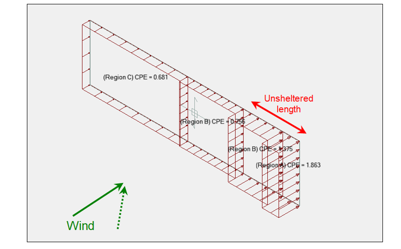
Of course, the alternate oblique wind direction should be considered as well:
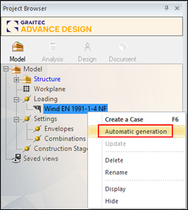
The climatic generator Advance Design is able to automatically detect the potential upwind walls and to compute the corresponding shelter factor for each wind direction.
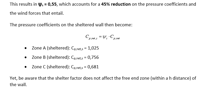
On the picture below, Advance Design detected that the wall under consideration could benefit from the sheltering effect of an upwind wall for the Y+ wind direction, resulting in ψs=0,55.
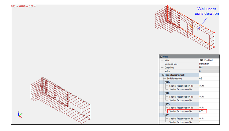
Yet, no such walls were detected in the other directions, resulting in ψs=1,0 for the X+, X- and Y- directions.
4. Conclusion
When designing a wall or a fence for climatic actions, the determination of the shelter factor can be a lengthy and tedious process, yet totally worthy as it can allow for a significant reduction of the wind forces.
Fortunately, in Advance Design, the detection of the potential upwind walls with the shelter factor they produce, is performed instantly during the automatic wind generation.
Learn more about Advance Design!
Visit website – https://graitec.com/advance-design/
Visit Advance Design Virtual Stand – https://graitec.com/advance-design-virtual/
Linkedin – https://www.linkedin.com/showcase/advance-design-&-advance-design-connection/
Free trial – https://graitec.com/free-trial/