Precise and intuitive steelwork functions are the result of over 25 years of experience in structural analysis. When it comes to modeling, analyzing and optimizing steel structures, Advance Design is a high-end solution that integrates all these processes within the same modern and easy-to-use interface.
Available standards
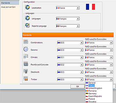
The Steel Design Expert performs an advanced analysis and optimization of steel elements according to the selected standards. The available steelwork standards are CM66 (France), NTC 2008 (Italy), ANSI/AISC 360-10 (USA), CAN/CSA S16-14 (Canada) and Eurocodes 3 with several national appendixes:
- France
- United Kingdom
- Romania
- Germany
- Poland
- Slovakia
- Czech Republic
- General
Complete libraries of materials and cross sections
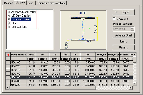
Advance Design provides complete libraries of materials (e. g., EN 10025-2, EN 10210-1, EN 10219-1) according to chapter 3 of EN 1993-1-1 and the possibility to define materials with custom properties. For cross sections, libraries such as European Profiles, Otua, UK Steel Sections and Autodesk Advance Steel Profiles are available. Also, you have the option to define libraries with customized cross-sections and even compound cross sections.
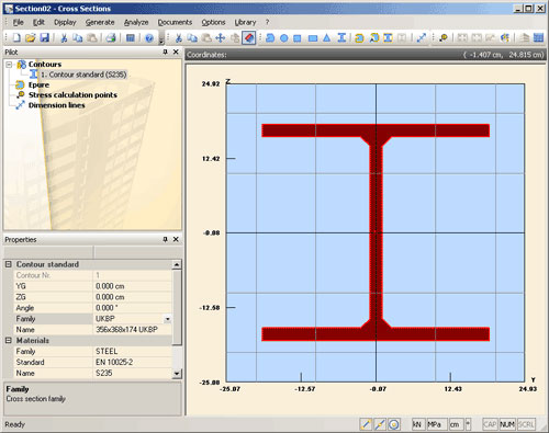
For advanced editing, visualization and calculation of geometrical characteristics of any type of cross section, Advance Design provides a specialized module: Cross Sections. This module can base the calculation (including torsionnal inertias and shear reduced sections) either on analytical formulas or on finite element analysis depending on the complexity of the cross section.
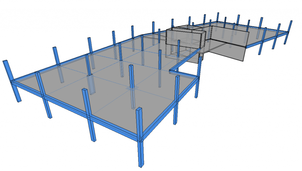
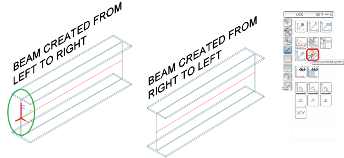
Advanced modeling
A large number of CAD functions are available for the easy modeling of steel structures. In addition, it is possible to automatically create trusses, portal frames and vaults which are available in Advance Design libraries. Using the corresponding structure generator, you can define the origin and the dimensions of the structure, the material and cross section of the elements, etc.
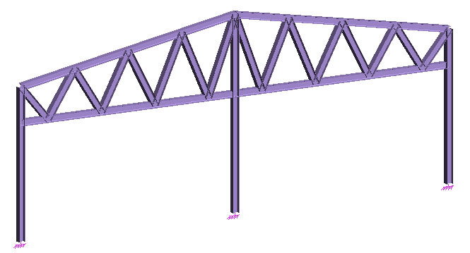
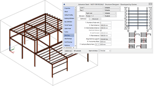
Since the version 2017, Advance Design includes the Steel Structure Designer. The Steel Structure Designer incorporates an extensive range of building definitions and tools enabling users to configure complete structures in seconds, from standard building shapes used in industry (platforms, steel halls), to more complex models, such as office buildings or structures with curved roofs, in seconds.
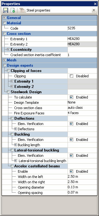
Complete customization of steel elements properties
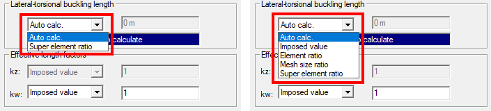
The properties list for steel elements includes all the required parameters for deflection, buckling and lateral-torsional buckling verification. Castellated beams can be defined and designed with the ACB+ module (Arcelor Cellular Beams).
Detailed calculation assumptions
The calculation assumptions referring to the steel elements attributes can be defined for each element or selection of elements, using the corresponding element(s) properties list.
For a fast definition of the steel elements properties, you can define design templates that can be applied on a selection of elements. Several design templates can be used in the same model. The design templates can be saved as XML files and imported in different projects.
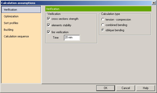
The calculation assumptions referring to the calculation type, the steel optimization, the buckling parameters, the calculation sequences, etc. can be globally defined through a single operation, for all steel elements of the model:
The design assumptions can be modified at any time, in the modeling step and in the analysis step (when modifying the assumptions during the analysis step, it is necessary to rerun the steel calculation).
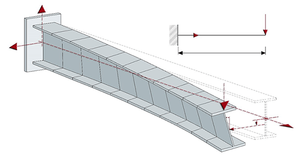
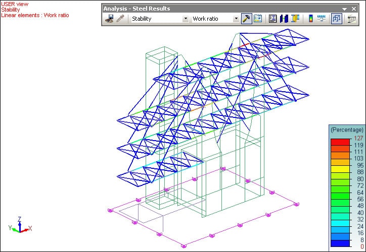
Accurate steel verification
The steel expert performs the steel verification, including the automatic buckling length computation and the automatic classification of cross sections according to Eurocodes 3. It provides access to results concerning the deflections verification, the cross section resistance, the element stability (buckling and lateral-torsional buckling) and the optimization of the steel shapes.
The command line informs about each step of the process. If errors are found during the calculation, the verification messages are displayed on the command line along with the IDs of the elements to which the messages refer.
When the calculation process is completed, you have access to advanced result verification and a multitude of tools for customizing the display of the graphic results in the most suitable way.
Reliable fire verification
Advance Design can perform the fire verification of steel elements according to §4.2 (simplified method) of EN 1993-1-2 as fire resistance (§4.2.3) and critical temperature (§4.2.4).
The software compares efforts given by frequent combinations with the maximum effort the element can handle at a given temperature.
The definition of the fire verification conditions is a fast and easy process. You only have to:
- Specify the fire exposure period:
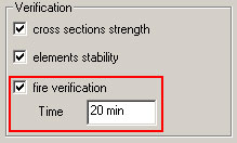
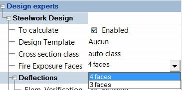
- Select the number of faces exposed to fire:
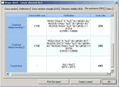
When the calculation is completed, the work ratios given by the fire verification are displayed on a specific tab of the shape sheet.
Maximize the efficiency of the materials consumption
The optimization process offers solutions for an efficient management of the materials consumption.
You have full control of the optimization conditions: you can define the optimization mode, the suggestions process, the iteration process, etc.
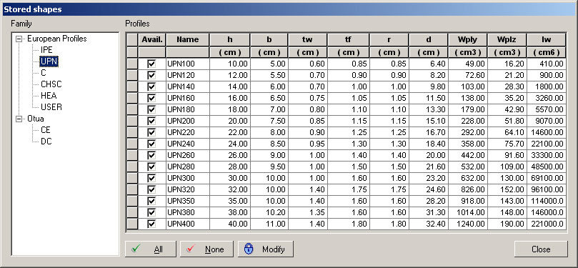
The Stored shapes command allows you to configure the list of available shapes from which the steel expert may choose the optimal ones.

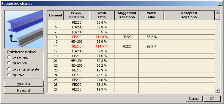
The steel expert compares the work ratio of the steel elements and suggests (if necessary) more adequate cross sections, that would correspond to the defined conditions.
For better visualization, the elements with a higher / lower work ratio than specified are displayed in red.
Advanced calculation reports
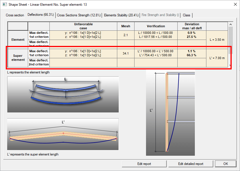
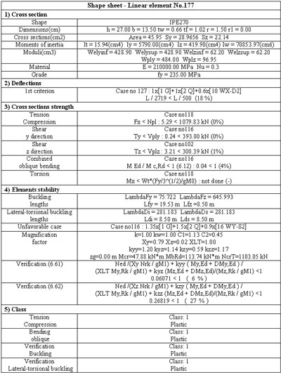
The shape sheets command allows you to view all the available results for a selected steel element: cross section properties, deflections, strength, stability, fire resistance and cross section class according to Eurocodes 3 in one dialog box.
You can generate a report with these results starting from the element’s shape sheet. This result is complete with all verifications and also mentions the corresponding article in the Norm.
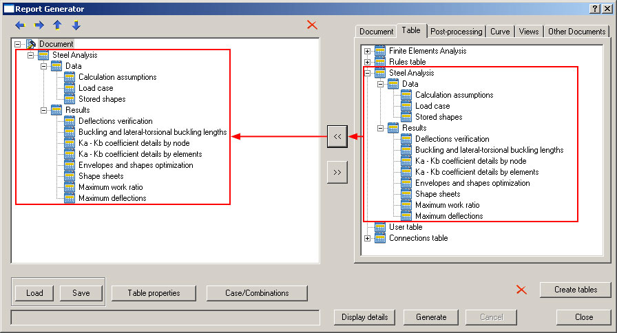
The steel verification report offers a complete diagnosis of the model in different outputs: tables, texts, graphical post-processing. The report can be customized to suit your requirements.
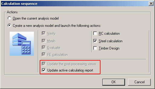
Advanced calculation reports
Once the report content has been defined, there is no need to recreate the calculation report when the model undergoes any modification. The report content, including post-processing views, automatically updates at each calculation iteration (if specified) while preserving all the settings previously made: