Design of Masonry Walls in Advance Design


by Kamil Dziedzic
Solution technical specialist

Abstract

In this article you will see how our new Masonry design module can handle walls modeled in Advance Design.

Keywords: #AdvanceDesign #Masonry

Starting with Advance Design 2023 you can model and design Masonry Walls according to Eurocode, NTC and CR6 codes. In order to correctly cover full approach following novelties were implemented:

  • FEM calculations – in the definition of masonry materials (single/two-layer/re-layered, slotted hollow/filled);
  • FEM calculations – in the definition of rotary/translational edge releases, including single-sided compression/tension releases;
  • Design of walls defined in the FEM model in the new design module according to codes;
  • Design of walls in standalone design module application for a wall defined and loaded separately by the user (without the FEM model).

1. Definition of masonry material in Advance Design

Advance Design 2023 implements a new material family – MASONRY, along with reference to relevant national standards, for example Eurocode 6 together with national annexes. Within this family, it will be possible to define walls of various types in terms of their construction – single-layer (including stiffened), two-layer, façade, cavity walls (filled or not). The type of wall will affect the mechanical parameters of the material, such as the strength parameters of the wall, but also stiffness. Thanks to this, it will be possible to define multi-material walls and you will not have to worry about determining their parameters yourself. In addition, a database of masonry units and mortars was implemented.

2. Masonry design module in Advance Design

Due to the fact that the masonry dimensioning has been implemented in accordance with our current philosophy, 2 work scenarios will be available as a dimensioning module – the use of the module on elements in the FEM model as well as the independent launch of the application, where the user, by defining the geometry of the wall and loads, will calculate any part of the wall without need to create a complex FEM model. So far, other reinforced concrete modules such as beams, columns, footings, etc. have worked on the same principle.

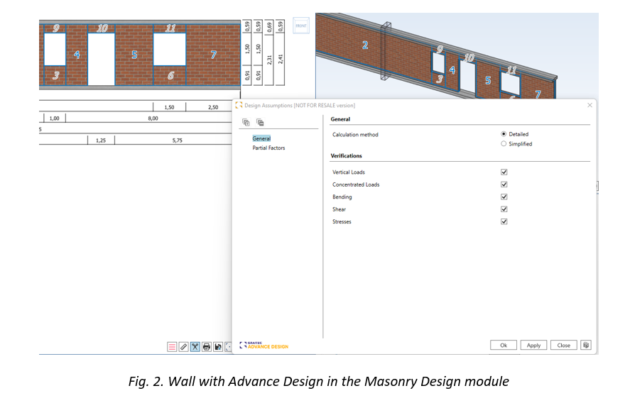
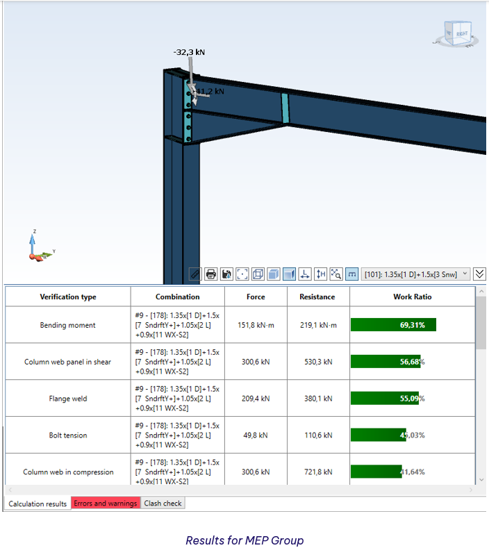
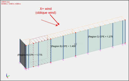
When working with a masonry wall in Advance Design, the key is how to transfer this wall to the module – as you can see, all pillars can be designed within one element. Working with the module itself looks identical to the existing reinforced concrete modules.

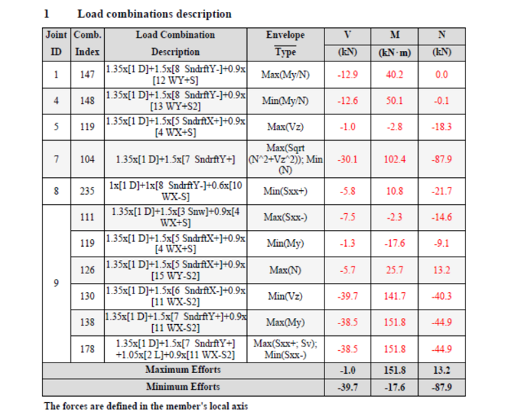
The method of determining the design forces is also interesting – strip method was used here, which was also used earlier as one of the possibilities of design RC slabs.

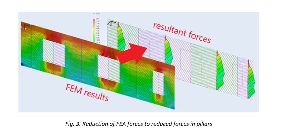
Thanks to this, FEM forces are converted into resultant forces reduced in the pillars. But importantly, the user will also be able to manage the width of the integral and enter their own panel division.

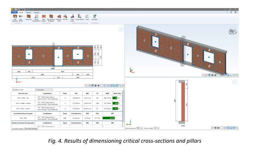
3. Masonry design according to Eurocode 6

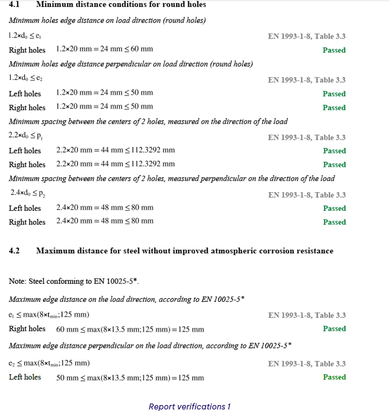
On the basis of the above reduction or on the basis of external loads (in the standalone version of the module), the pillars are dimensioned according to the provisions of Eurocode 6 (or Italian NTC/Romanian CR6). Both detailed methods according to part 1 of the standard as well as simplified methods based on part 3 may be used.

The external and internal walls of the basement floors, intermediate and highest, are designed.

The scope of calculation is the design of walls:

  • loaded mainly vertically
  • under concentrated load
  • for bending from loads perpendicular to the plane of the wall (e.g. wind/ground pressure)
  • for shear in and out the plane of the wall.

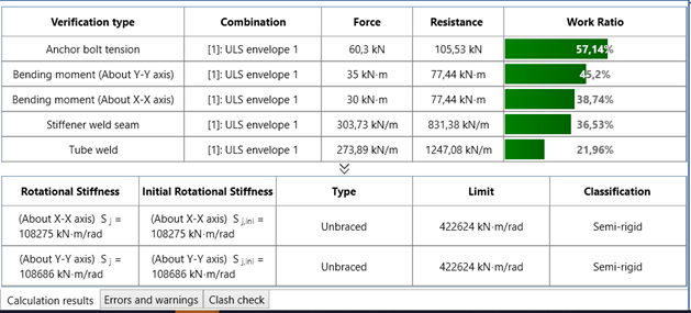
In addition, the stresses can be verified  according to the classic principles of mechanics. The user will be able to indicate whether he wants to carry out all or only selected verifications, and the results will be presented for the worst or specifically indicated pillar.

Learn more about Advance Design!

Visit website – https://graitec.com/advance-design/
Visit Advance Design Virtual Stand – https://graitec.com/advance-design-virtual/
Linkedin – https://www.linkedin.com/showcase/advance-design-&-advance-design-connection/
Free trial – https://graitec.com/free-trial/

Advance Design Steel Connection – part II Advance Design                            


by Adriana Gherlan
Steel PowerPack Manager

Abstract

This article is the second one in a series of 3. In this series, you will find basic information about Advance Design Steel Connection: what it is, how it can be used, and which are the main features of the module.

This second article will explain how to use the Advance Design Steel Connection module in the Advance Design environment.

Keywords: #steeldesign #connections #advancedesign

1. Advance Design environment

Advance Design allows the creation of different types of connections between the steel profiles. Connections can be created in the modeling step and the analysis step as well. Advance Design also performs the connections errors verification. The verification function, available anytime during the modeling and also at the creation of the analysis model, displays in the command line the connections modeling errors and warnings (if any).

2. Create connections in Advance Design

The creation of the connections between steel members is very easy. Once the steel structure is defined the connections can be added.

The connection types are available in the contextual menu at the right click based on selection or the ribbon.

Connections – Contextual menu

Adding connections using the contextual menu, is done by selection. For example, if we want to add the base plate connection for all the columns, just select all the columns and choose the base plate from the connection list. This will instantly add all the base plate connections for all selected columns.

For an APEX connection selecte all the rafters and from contextual menu choose the corresponding connection: Connections -> Create on selection -> Fixed Connections -> Beam-Beam fixed connection

Therefore, in less than a minute the connections are created within the Advance Design model.

3. Group Connections in Advance Design

The option for Group connection is created to boost productivity and optimize the workflow.

To group the connections, select the connections you want to have in one group and do a right-click to access the contextual menu. From there choose the Connections -> Group.

More than that, the connections which are grouped will be renumbered to see from which group they belong.

4. Connection Design

Once the calculation is done, in the Design tab of the Advance Design Pilot, we can find the Connections. As you will notice, only one type of connection is available for design.

Before opening one of the connections and starting to design it, you must not forget to check the different options available for the Design Modules, including the Advance Design Steel Connection:

Based on the selected options, different loads and envelopes will be transferred to the steel modules:

  •  Always transfer user-defined envelopes to Design Modules for steel connections elements

This option should be checked in case you have specific envelopes defined by you and you need them in the steel connection design

  • Export loads to design modules – Load cases and corresponding efforts diagrams/torsors

This option will export just the load cases and the corresponding efforts per load case.

  • Export loads to design modules – Load cases and corresponding efforts diagrams/torsors with the list of combinations

Besides the load cases and efforts, this option will export also the combinations.

  • Export loads to design modules – Load cases and corresponding efforts diagrams/torsors with the list of combinations + combination values of efforts diagrams/torsors

This last option will export also the combination values of the efforts.

An example of the MEP Connections will be shown further.


The geometrical configuration of the connection is similar to the standalone application but accessible from one single button on the ribbon: Geometry.

The Geometry button is regrouping in the Advance Design environment all the independent dialogs from the standalone application, in one dialog with multiple tabs.

The GUI of the tabs is identical to the one from the standalone module, offering the user the same smooth experience.

After the geometrical configuration is set, the Design Settings must be checked to make sure everything is according to the user project.

In the Design Settings, one particular option will define with which efforts the joints will be designed, the Combinations option. This option offers two possibilities: All Combinations or Envelopes.

All Combinations – the joint will be calculated with all existing combinations. Depending on the number of combinations, and in this case the number of connections grouped, the calculation can take longer than usual. For example, if we have 10 connections and 100 combinations, 1000 calculations will be performed.

Envelopes – the joint will be calculated with the combinations that provide the maximum efforts. The criteria to choose these combinations are different from one type of joint to another and will be always available in the Report under the chapter Load Combinations description.

For the MEP group, we are showing in this article, these are the criteria and the corresponding envelopes used to verify all the connections from the same group. As we can see, instead of 100 combinations for each joint, we have only 11 envelopes.

Once the Design settings are defined, the calculation can be run and the main results will appear in the console of the module. In case of warnings or/and errors, the corresponding tab will be highlighted.

If everything is ok, the drawing can be generated. This is done automatically while clicking on the Interactive Drawing tab available in the top left corner of the main window.

The report generation is similar to the standalone module. On the Ribbon, we have the Report Settings button, which allows the configuration of the content we want to have in the report. Here, the user can choose what chapters to include in his report.

Next to the settings, the Generate Report button is available. The report can be generated in PDF or DOC format, depending on the needs of the user.

Learn more about Advance Design!

Visit website – https://graitec.com/advance-design/
Visit Advance Design Virtual Stand – https://graitec.com/advance-design-virtual/
Linkedin – https://www.linkedin.com/showcase/advance-design-&-advance-design-connection/
Free trial – https://graitec.com/free-trial/

Advance Design Steel Connection – part I The Basics


by Adriana Gherlan
Steel PowerPack Manager

Abstract

This article is the first one in a series of 3. In this series you will find basic information about Advance Design Steel Connection: what it is, how it can be used and which are the main features of the module.

Keywords: #steeldesign #connections #advancedesign

1. The History

The Advance Design Steel Connection module is the evolution of a French local product Melody Attache. Even if today GRAITEC French customers are using the local product, because of the evolution of the software industry, Advance Design Steel Connection was born.

 As I mentioned in a previous article, the Advance Design Steel Connection module has evolved over the years, the User interface has changed, and a wide variety of steel joints can be calculated according to the EC3 norm, in a fast way, efficiently covering many of the situations that can occur in the steel joint calculation.

This evolution of the module can be translated into an embedded application in Advance Design and a standalone application module. Therefore, when a user is installing Advance Design, the steel connection module will be available as well, within Advance Design or standalone.

Old Version of ADSC

Version 2023 of ADSC

2. What is Advance Design Steel Connection

The Advance Design Steel Connection module is a specialized and dedicated module for joint design, using analytical methods according to Eurocode 3. The module is part of the Advance Design application and can be run inside Advance Design and as a standalone application.

In my last article, I have presented all the connections available in the steel connection module, connections documented in Eurocode 3, with specific analytical methods. Let’s have a brief review of the connections offered by the design module: Base Plate, Tubular Base Plate, Moment End Plate, Apex Haunch, Clip Angle, Gusset, Splice, HSS Bracing, Gable Wall End Plate.

3. How to use Advance Design Steel Connection based on environment

The Steel Connection module can be run together with Advance Design, allowing the user to design the specific connection directly from the Advance Design model without exiting the application.

Another way to use the module is as a standalone application, allowing the user to design the one by one the joints.

A. The Standalone environment

After the installation of Advance Design, besides the icon of the main application Advance Design, a folder is created: GRAITEC Advance Design modules. Inside this folder, the Advance Design Steel Connection icon is available, to launch the standalone application.

Once the application is started, the starting page will appear from where the user can set up the Localization, create a New file, Open an existing one, or select a predefined template from the available list for Types of connections.
Start Page

After choosing a type of connection, the user can start to configure it as needed. The accessible user interface offers all tools needed to achive the requirements.

Example of joint in standaloane

Configuration dialogs – Geometry

Once the geometry is configured, the design assumptions, the combinations and the loads can be set using specific dialogs.

Configuration dialogs – Design assumptions and Loads

As everything is set the calculation can be lunched and the results can be check quickly using the results bar available in the bottom left corner of the application window.

Results on standalone

As any other design module from GRAITEC, the results and all the geometrical details, including loads, can be checked in a simplified or detailed report. Also, the report can be generated in a DOC or PDF file format.

Report settings

I must specify that the detail report contains all formulas and articles pointing to Eurocod chapters.

Here below we can see an example of the Compression resistance of the column verification. As you notice, the chapters from Eurocode are listed on the right side of the report, in line with the specific verification.

Compression resistance of the column

As I mentioned at the beginning of or the article, this is the first one in a series of 3.

Don’t miss the next one, where I will talk about how to use the steel connection module in  Advance Design enviorement.

Learn more about Advance Design!

Visit website – https://graitec.com/advance-design/
Visit Advance Design Virtual Stand – https://graitec.com/advance-design-virtual/
Linkedin – https://www.linkedin.com/showcase/advance-design-&-advance-design-connection/
Free trial – https://graitec.com/free-trial/

Wind action on free-standing walls at the Eurocode 1


by Thibaut FRETTÉ
Product Technical Specialist

Abstract

In this article, we will apply the procedure from the EN1991-1-4 to estimate the wind forces on a free-standing wall with a return corner.  

Keywords: Advance Design, wall, free-standing wall, Eurocode 1, EN1991-1-4, return corner

1. Introduction

Free-standing walls are covered in §7.4.1 from EN1991-1-4.

This part is intended towards fences as well as buildings with so many openings that they should be designed as per §7.3 (canopy roofs) and §7.4 (free-standing walls).

2. Theory

The Eurocode 1 defines two types of free-standing walls:

  • Without return corner
  • With return corner
Free-standing walls will be divided in A, B, C and D zones, depending on how long they are.

Pressure coefficients for each zone are determined from Table 7.9 and may require up to 3 successive linear interpolations based on:

  • The dimensions of the wall (Length/Height ratio)
  • The length of the return corner (if any)
  • The solidity ratio of the wall (also called opening ratio or porosity)

3. Example – Free-standing wall with return corner

Assume a free-standing wall (Length: 16m and Height: 4) with a 0,9 solidity ratio.

This wall has a 2m-long return corner.

3.1.            1st linear interpolation
We perform a 1st linear interpolation based on the length/height ratio of the wall (ignoring the return corner).

Yet, the values we have just obtained (in red) only stand for a wall without a return corner.

A 2nd linear interpolation is then required.

3.2            2nd linear interpolation

We perform a 2nd linear interpolation based on the length of the return corner (noted L’).

Yet, the values we have just obtained (in blue) only stand for a solid wall (φ = 1).
A 3rd and final linear interpolation is then required.

3.3.            3rd linear interpolation

We perform a 3rd linear interpolation based the solidity ratio of the wall.

The values we have just obtained (in green) are the ones we should expect for the A, B and C zones (the wall is not long enough to get a D zone).

There are the values the climatic generator from Advance Design 2023 will return:

Of course, Advance Design will consider all required wind directions (perpendicular and oblique winds).

Advance Design will also consider more complex effects, such the potential force reduction that can be benefited from an upwind wall, through the shelter factor (ψs) defined in §7.4.2:

4. Conclusion

The estimation of wind forces on free-standing walls sure is a tedious process, with a high risk of errors due to the various linear interpolations needed.

Fortunately, version 2023 of Advance Design now handles these structural elements, generating the corresponding forces on your 3D structures in a single click.

Learn more about Advance Design!

Visit website – https://graitec.com/advance-design/
Visit Advance Design Virtual Stand – https://graitec.com/advance-design-virtual/
Linkedin – https://www.linkedin.com/showcase/advance-design-&-advance-design-connection/
Free trial – https://graitec.com/free-trial/

Increase calculation speed in Advance Design 2023


by Mateusz BUDZIŃSKI
Structural Analysis Product Line Manager

Abstract

 In this article, you will find out what impact the changes made in the latest version of Advance Design have had on computation time.

Keywords: Advance Design, 2023 release, Performance, Calculation time

Introduction

The latest version of Advance Design brings a great number of changes and enhancements in many fields of the program. One of the most visible changes are improvements related to the speed of computation and the way data is stored. This short article will show the impact of these changes.

Description of changes

To help increase productivity time in Advance Design, we have worked hard to improve several areas, which translate into much faster calculation times, as well as reduced file sizes of the results.

Three areas have been changed:

  • Improvement of the calculation solver and program architecture

These changes consisted in the optimization of operations, thanks to which the speed of the FEM calculations has been increased.

  • Changed the way results for combinations are calculated

Previously, the results for each linear combination for each node were determined and saved to a file during the calculation. Now the results are calculated while displaying the results, which has dramatically reduced the size of the project on disk as well as significantly reducing the computation time. At the same time, the increase in the generation time for graphical results is unnoticeable.

  • Optimization of verification procedures for steel and timber elements

These changes concern the design procedures for steel and timber linear elements, resulting in a significant reduction in design time. Although some changes and improvements are common to all standards for steel and timber design, special attention has been given to design procedures for members according to Eurocode 3 and 5.

Examples

Below are 5 examples that illustrate the changes between the current and the previous version of the program regarding FEM calculations, steel/wood design and the weight of the result files.

 The average increase in performance

The above models represent an approximate range. However, the effect is global and independent of the nature and size of the model. The table below, shows the aggregate results for the decrease in the required time, as well as the decrease in size of the project file compared to the previous version of the program for a sample of 15 various models of different sizes and computational range.

Note that the above values are averaged and may vary depending on the number and type of elements, the number of load combinations and the type of analyses performed. The smallest impact of changes is seen on smaller structures with a small number of combinations but complex types of analysis (for example nonlinear). The greatest benefits can be seen for large structures with a large number of linear combinations.

Learn more about Advance Design!

Visit website – https://graitec.com/advance-design/
Visit Advance Design Virtual Stand – https://graitec.com/advance-design-virtual/
Linkedin – https://www.linkedin.com/showcase/advance-design-&-advance-design-connection/
Free trial – https://graitec.com/free-trial/