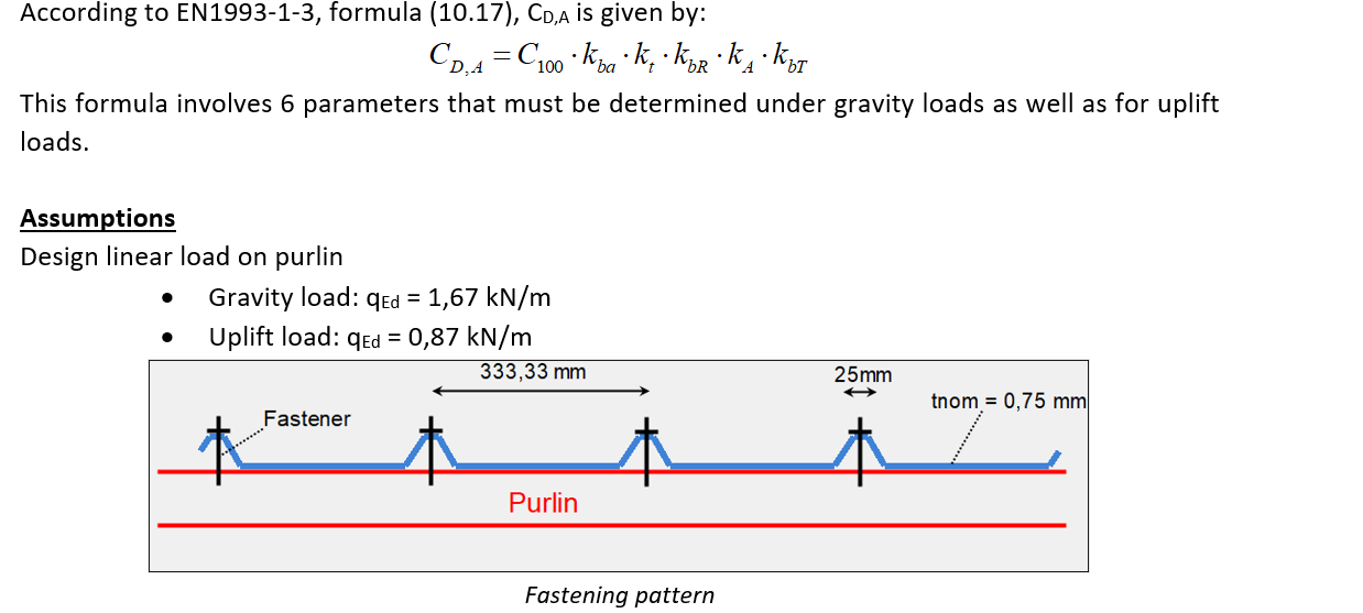
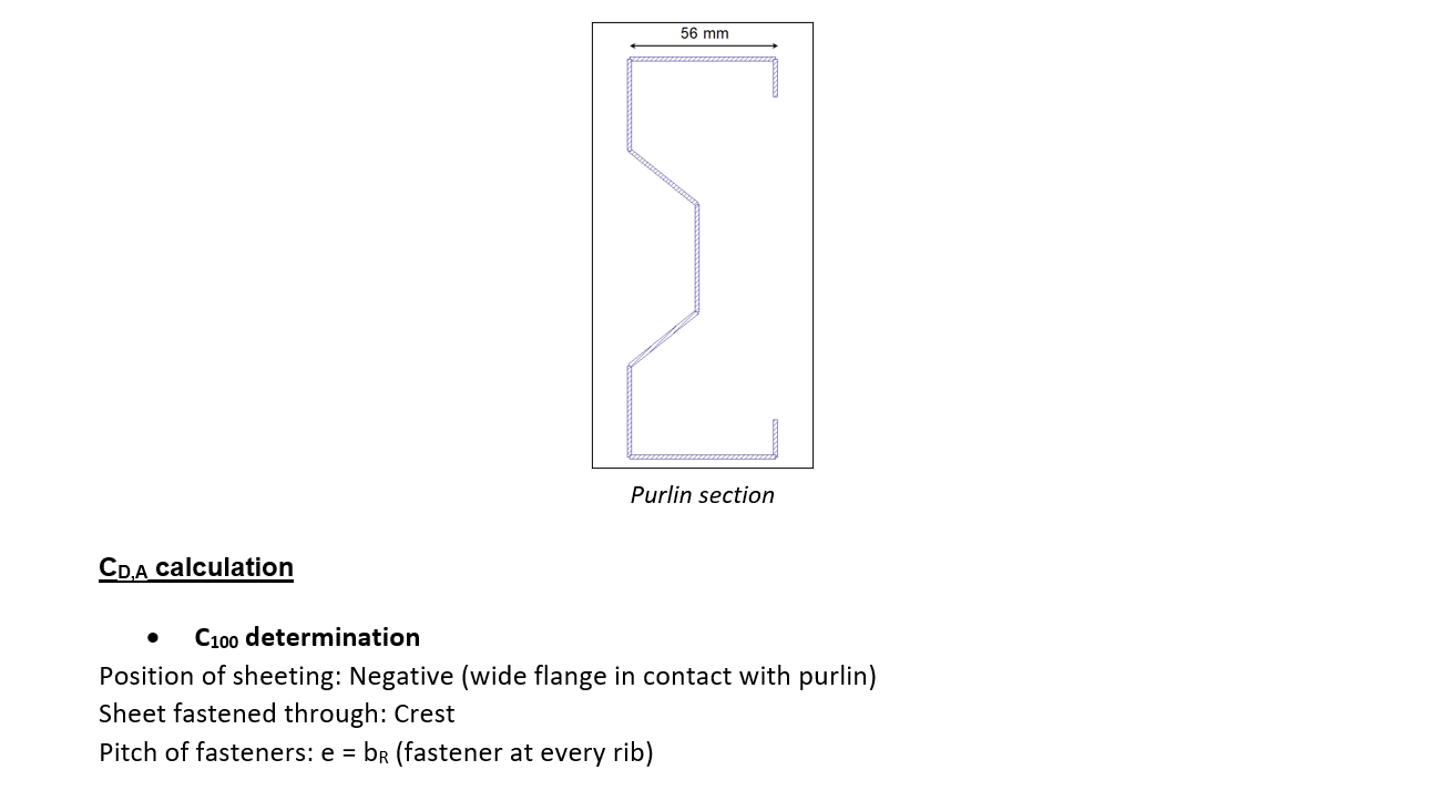
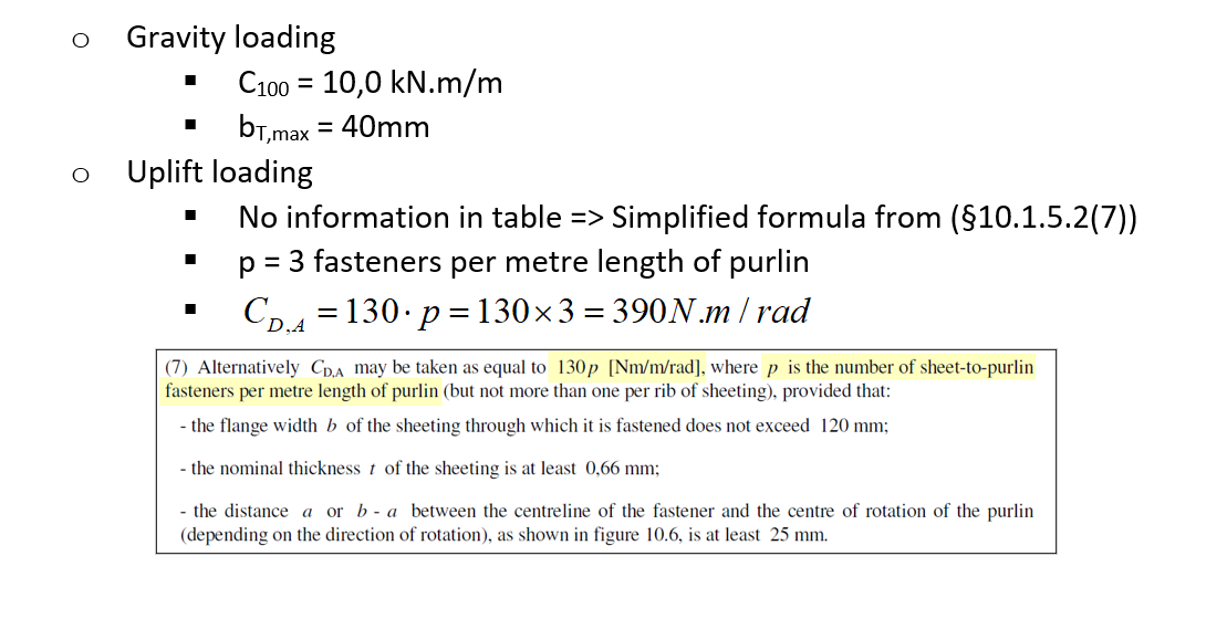
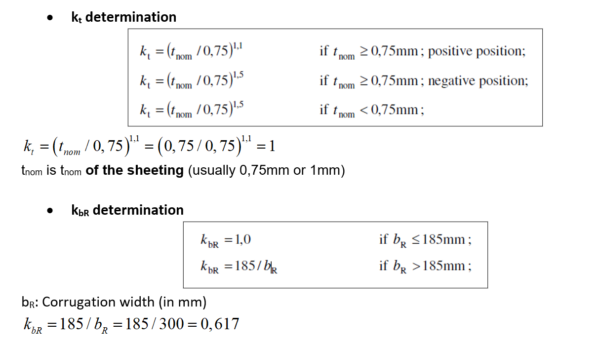
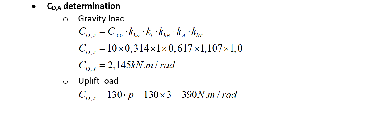
The following example shows how to estimate the rotational stiffness of a trapezoidal sheeting connected to the top flange of a purlin (CD,A) as per EN1993-1-3.
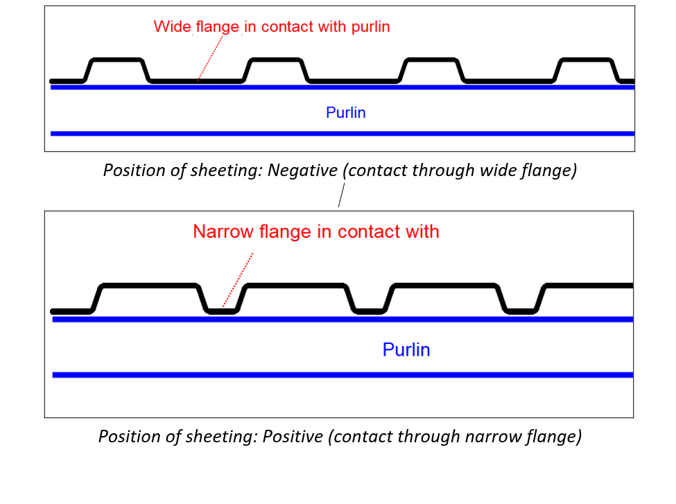
Note: Position of sheeting positive / negative
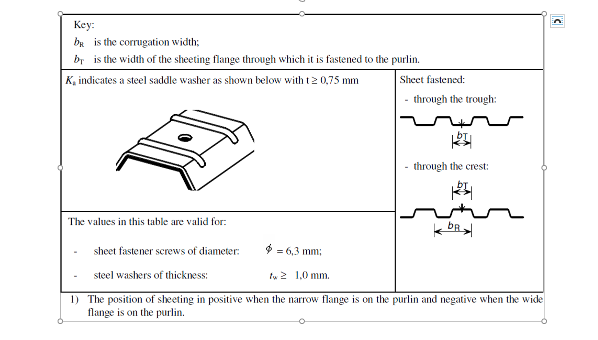
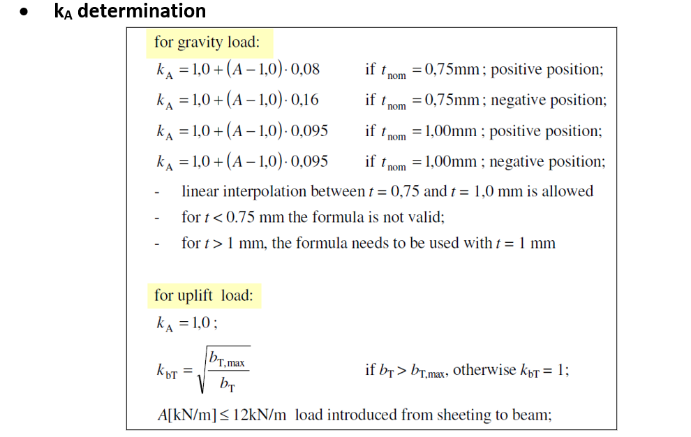
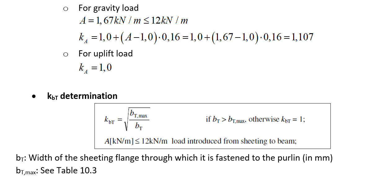
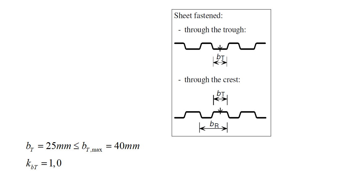
bT: Width of the sheeting flange through which it is fastened to the purlin (in mm)
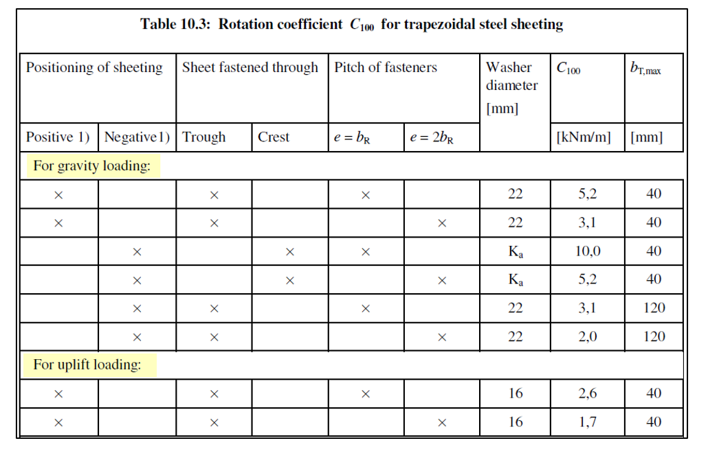
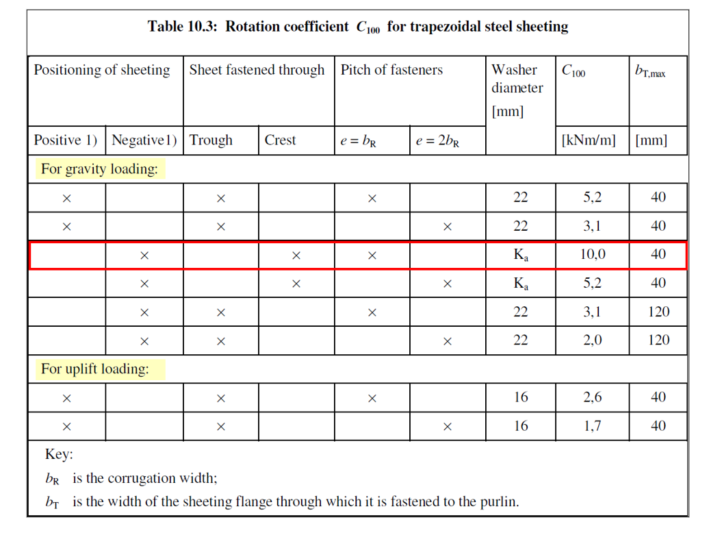
bT,max: See Table 10.3
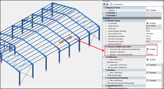
In Advanced Design, the rotational stiffness from sheeting to purlin can be considered when the Advanced Stability feature is enabled:
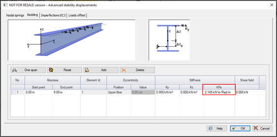
The CD,A rotational stiffness can then be specified in the bedding tab, as the KRx component:
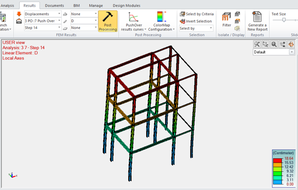
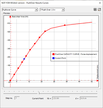
The Pushover is a static nonlinear analysis in which the structure is pushed gradually following a predefined load pattern distribution. Material nonlinearities in structural elements are usually modeled by concentrated plastic hinges and the option for including geometrical nonlinearities is available.
A control node, generally located at the top level of the structure, is considered to monitor the lateral displacement while the load is increased. The base shear is plotted Versus the control node lateral displacement and the resulting graph is called the Pushover curve.
The pushover curve represents the structural capacity to resist lateral loads and for this reason it is also called the capacity curve. On the other hand, the adequate seismic response spectrum represents the seismic demand and is also referred to as the demand curve.
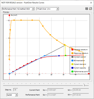
The purpose of the pushover analysis is to determine the maximum structural nonlinear response to seismic loads. This extremum is provided in the form of maximum control node displacement. Then, based on its value, the location and plastic limit state of hinges are determined and the inter story drift is checked.
The sought maximum response is found at a point that balances between the structural capacity and the seismic demand. This point is called Performance Point and in Advance Design it can be calculated according to the Eurocode 8 N2 method or the ATC-40 Capacity Spectrum Method (CSM).
Graitec PowerPack propose a specific command for assigning reinforcement to a layer (for example Top or Bottom) for easy and quick filtering of the reinforcement.
The layer might refer to a geometrical location of reinforcement but also to another purpose, such as its function.
The information about the assigned layer is stored using shared parameters: G.Rebar Location for Structural Reinforcement and G.Fabric Location for Structural Fabric Reinforcement.
The assignment is done automatically and manually. The automatic method is applied during reinforcement generation using calculation modules or reinforcement generators in PowerPack. For example, the top bars in the foundation have an automatically assigned value T (a default name for a top reinforcement). This automatic assignment is made to the selected rebars, for example in the case of a foundation to the lower and upper bars in the pad.
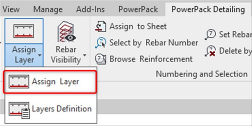
The manual assignment is done for selected reinforcement using the Assign Layers command, which is available in the PowerPack Detailing ribbon.
The Assign Layers command opens a special dialog with the list of default/predefined layers.
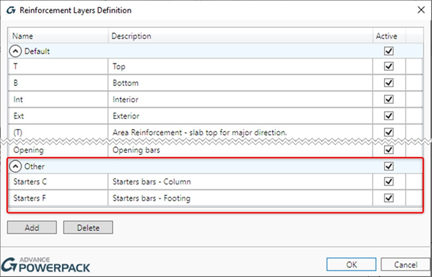
The content of the list is based on the configuration from the Reinforcement Layers Definition window, opened by the Layers Definition command. The user can modify names for default layers, use the Active option to limit the list of layers that can be available during the assignment and add new positions/layers to the Other group.
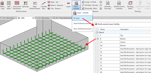
The value of the layer parameter is mainly used in the new options of the tools for controlling the reinforcement visibility. Indeed, to the Rebar Visibility functionality, a new group of options for selecting by layers is added.
When the Top or Bottom option is selected, then an additional filtering for reinforcement is activated, respectively by the top and interior or the bottom and exterior layers. When the Selected option is active then the selection of layers for displaying is done through the dialog opened by the Select Layers button.
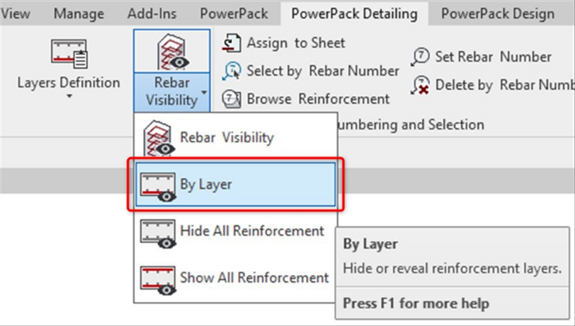
In addition, three commands are available under the drop-down list under the Rebar Visibility: By layer, Hide All Reinforcement and Show All reinforcement.
Hide All Reinforcement and Show All Reinforcement allow you to quickly turn off or on the visibility of the entire reinforcement in a given view. By Layer allow you to quickly select the reinforcement to be displayed by using the Layer property.
This is particularly useful when generating drawings with separate views, e.g. for bottom/ top reinforcement for slabs or foundations.
Article by Stevens Chemise / BIM Industry Manager / GRAITEC France
During the last few years, the Advance Design reinforced concrete modules have been progressively getting more and more configurable for automatically generated reinforcement. New customer-specific settings are added in each version, making the modules for RC beams, RC columns, RC foundations as well as RC walls and RC slabs more and more configurable. This allows you to set the parameters in such a way that the reinforcement for the elements is generated according to your expectations. And of course the expectations on the reinforcement of an element can be different, depending on the user and sometimes on current needs. Sometimes in one project the focus is on the optimum use of the reinforcement and in another on the ease and speed of construction.
Today, let’s look at a few selected reinforcement settings for reinforced concrete beams.
Common longitudinal reinforcement for the spans
Imagine that we have a reinforced concrete beam with several spans. We have modeled and calculated it as a continuous beam, and we want to generate the longitudinal reinforcement for each span separately. This is the default setting of the module.
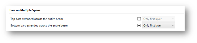
But if we want to get the effect of continuous longitudinal reinforcement on all spans we can get it very simply. In the window Reinforcement Assumption on the Longitudinal Bars tab we have dedicated options ‘Bars on Multiple Spans’.
The option Top/Bottom bars extend across the entire beam can be enabled independently for longitudinal bottom and top reinforcement. Additionally, you can select whether you want to extend bars from the first layer only or also bars from all layers (if any).
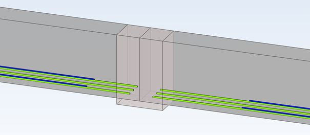
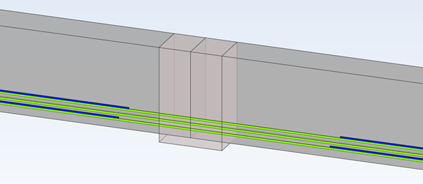
Let’s take a look at the examples in the pictures below (only the main bars of the bottom reinforcement are shown for easier understanding).
Option for extending is disabled (default setting) – bottom bars are independent on both spans
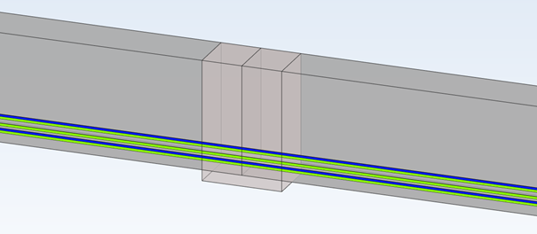
The first layer is extended
All layers are extended
Linking of longitudinal members with transverse reinforcement
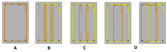
One of the settings for transverse reinforcement is the default shape type of these bars. In the Reinforcement Assumptions window on the Transversal Bars tab, we have a number of useful options for setting shapes. One of them is the possibility of deactivating the automatic selection of shape types and the possibility to choose from the list the type of transversal reinforcement – and actually the way of joining the longitudinal bars not located in the cross-section corners. We have 4 types available, as on the pictures below: A – None, B – Stirrups, C – Pins and D – Multiple links.
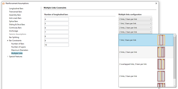
Note that multiple links for this case can have two solutions: with one large and one small stirrup or two identical ones. When we can have more longitudinal bars in a layer (than 4, as is the case on the above picture), the number of possible configurations for multiple links is larger. This can also be set according to our needs in the Multiple Links tab where we can graphically choose default settings for different number of longitudinal bars.
Maximum number of longitudinal bars
One of the reinforcement settings is the number of members of the longitudinal reinforcement to be generated due to the width of the beam cross-section.
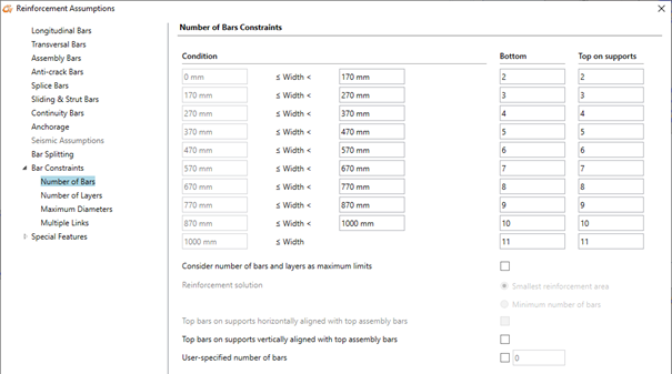
These settings are available in the Reinforcement Assumption window on the Numbers of bars tab. We can set there the number of longitudinal bars in the span and in the support for different width ranges of the cross-section.
So for example if the cross-section is 300 mm wide, 4 longitudinal bars (in the span and in the support) are taken automatically. Depending on the required calculated theoretical reinforcement, the program will then select the diameters of these bars and if necessary, add additional layers of bars. But among the options available in this configuration window we can also find a special option that changes the way of determining the number of longitudinal bars. It is called Consider number of bars and layers as maximum limits. When this option is not active, the entered number of bars is considered as imposed. When this option is active, then the number of bars is considered as maximum allowed value and the number of bars will be automatically determined based on required reinforcement area.
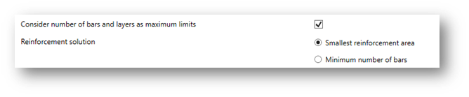
As the selection of this method for a given required reinforcement area can lead to a variety of possible solutions, e.g. fewer members with larger diameter or more members with smaller diameter, two options are additionally available for choosing the preferred solution:
Smallest reinforcement area – will assure the smallest difference between the real and the theoretical reinforcement area.
Minimum number of bars – will assure the minimum number of longitudinal bars and will eventually lead to bigger diameters.
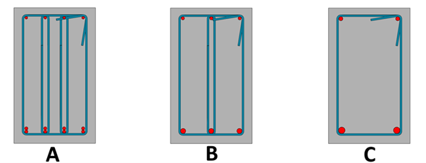
Typically, both options produce fewer bars than the fixed number of columns method, especially when the second option is chosen, but the end result also depends heavily on other assumptions. We can see a simple example for a cross section having 300 mm with three different settings used: A – the number of columns of bars is fixed (which gives 4 columns of bars for this width), B – the number of columns of bars is a maximum limit, and the first option “Smallest reinforcement area” is selected, C – as previously but the second option “Minimum number of bars” is selected.
Examples of different configuration of longitudinal bars in section for the same required theoretical reinforcement.
All these settings give different configurations for the number and diameters of longitudinal members, but they all satisfy the section verification requirements and give a larger area of real reinforcement than the required area of theoretical reinforcement.
The above settings are only a fragment of the possible settings. It’s worth to get to know all the settings, because thanks to the multitude of configuration options and the possibility to save them to templates, using design modules of Advance Design we can dramatically accelerate the daily work.
Article by Mateusz Budzinski / Technical Product Manager / GRAITEC