With the new release of the Powerpack for Revit 2022 we are launching the new rebar drawings generator.
In this post I am intending to explain the concept behind the tool, assumptions that were made in order to obtain the best results and at the end I will add some tips&tricks.
As you know, we already had a view generator in the Powerpack. There were 2 issues that were making the mechanism basically unusable:
- The mechanism used an external Revit file that contained the drawing configurations. Therefore, there was no initial link between the user’s Revit project and our drawing template. Of course, our template could have been customized but it would had presumed some time.
- In order to work properly, the rebar cage needed to be generated with the Powerpack so that rebars could have roles. After the generation, the mechanism knew the roles of the bars and knew what to do with them.
We decided to stray from this approach and we established the main pillars the mechanism will be based on:
- The mechanism will be totally based on the user’s Revit Template.
- It will use the active project’s view templates, detail view types and rebar schedules. It will read the Multi-Rebar Annotation, Tags and Title blocks families.
- The rebar cage inside the element can be manually modelled or generated by the Powerpack.
- The section of the elements will not be an issue. The mechanism will work the same for cast-in-place or pre-cast elements.
- We will implement the mechanism is such a way that it will take account of the user’s browser organization sorting rules by inserting Revit’s View parameters also.
- We will be able to generate wall drawings also.
In a few words, this is how the mechanism works:
- Using the drawing manager, the user will make his own drawing configurations for each category of elements (Beams, Columns, Walls, Foundations)
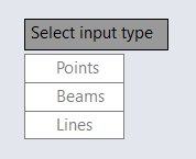
- The user will run the command and he will select the elements.
- After the selection is made, the grouping algorithms will decide if the elements can be treated as a group or not.
- The configuration dialog will appear, and the user is able to change the configurations.
Using the user’s Revit Template
This part of the implementation was easy-to-do. However, during the development we ran into the issue of multiple projects. We decided to not put the user to make the drawings configurations each time he starts a new project (Assuming that users have the same revit template).
We decided to create an .xml file that will contain all the configurations made by the user. This way, the settings will always be there when the user starts a new project. Of course, modifying the Revit template to a completely different one means that you should do the configuration again.
The .xml file is placed here: C:\Users\<User>\AppData\Local\Graitec\Advance Design modules\2022\Templates\Revit\DrawingConfigs
Furthermore, with this approach, the .xml file can be shared across the office. This way only one person needs to make the configurations.
Supported elements and Rebar cages
The mechanism will work the same for any Revit Family. We are not using any mapping mechanism. Any Loadable family will be supported. Model-In-Place elements are not supported.
We established that we needed to perform the drawings regardless of the method the rebar cage was obtained (by hand or generated by the Powerpack). In order to achieve this, we needed to use the Style of the rebar shape family.
Quick recap: The style of the shape can be Standard or Stirrup/Tie. There are no geometrical differences between these two, any rebar shape can be set as either of them. The difference comes from Revit’s rebar constraints mechanism. When placing a stirrup/tie bar, it will search for the nearest host rebar cover. Standard bars will additionally search for the stirrup bars handles. Basically, the Stirrup knows that it needs to tie Standard bars. This is especially helpful when modelling rebars by hand.
Thus, we are using the style of the rebar as an input parameter in order to know on which bars we are placing Multi-Rebar Annotation or for which bars we are generating bending details.
This is probably the most important point in order to achieve proper drawings.
Example:
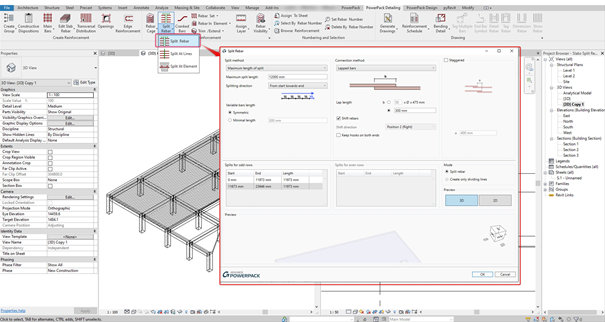
Drawing manager dialog
We needed to let the user configure his drawings according to his Revit template and requirements. The dialog will manage the Annotations, Bending details (General page) and drawing configurations (Element category pages).
In the following I will explain all the options inside the dialog.
General page
- Generate views only by default configuration – Checking this option will bypass the Create views dialog. The drawings will be generated according to the check at the left of the configuration in the left panel. It was intended to speed up the process.
- Name – The name of the annotation configuration. It will be further used in the drawing configuration
- Rebars – The rebars that the user wants to place Multi-Rebar Annotations on.
- Rebar Presentation – How the users wants to show the rebars in the generated view. Examples: Central bar, three in the middle…
- Multi-Rebar Annotation – The family that the user wants to use for this drawing. The list will contain all the MRA inside the project
- Group MRA – If the elements has multiple distribution of the same rebar number you can group the MRA in order to obtain a single distribution symbol. Example: For a beam with stirrups distributed on 3 zones you can obtain 3 MRA or only 1 MRA.
- Multiple Tag Family – On rebars that are not distributed, we are placing rebar tags using our own tag multiple bar command. The user needs to set what tag family he wants to use.
- Bending detail family – What family the user wants for the generated bending details
Drawing configurations:
- View type – what kind of drawing the users wants his configuration to contain. He can choose from a list that is different for each element category.
- Revit view type – We used detail views for the drawings. The user can choose what detail type he wants for his drawings. We considered that this option might be used also for the browser organization. The list will contain all the detail view types in the model.
- View Template – What view template the user wants to apply to the view. The list will contain all the view templates in the model.
- View scale – At which scale the user wants to generate the drawing. If the view template has the scale included, the value in the dialog will be ignored.
- Length ratio: Percentage of the length/height of the element at which the section/plan view/node detail will be generated.
- Annotation – the annotation configuration that the user wants to use in the drawing. The list will contain the configurations from the General page
- Bending detail – the bending detail configuration the user wants to apply to the view. The list will contain the configurations from the General page.
- Rebar schedule category – what type of rebar schedule do you want to generate for the select element (Structural Rebar, Fabrics etc.)
- Rebar schedule type – a template that will be used for the newly generated rebar schedules. The list will contain all the schedules inside the model according to the selected category.
- Titleblock - A list of all the titleblocks in the model
Revit View parameters and Browser organization
Advanced Revit projects are using a different browser organization rule. They are doing this with a combination of Revit View Parameters. We decided that the drawings should not be randomly generated and should take advantage of the user’s browser organization.
In order to do this, we needed to read the project’s view parameters and include them in our drawing configurations.
First you need to add them into the drawing manager by clicking on the “Manage” button. Some parameters might be included in the view templates definition, so you do not need to include all of them. After adding them in the drawing manager, for each configuration, at the end of the table, new columns will be added.
If you want all your drawings to have the same value for a parameter, you should insert the value into the drawing manager. However, if your values differ for each element, you should insert them into the Create Views dialog.
Grouping algorithms
Users have different ways of modelling in Revit so we needed to develop some connection algorithms that will allow us to group elements. Each element category needed to have its own grouping algorithms. Also, the grouping was made accordingly to the desired drawings.
We also took account of the design groups made in the Powerpack. Thus, if there are Multi-Span Beams or groups of Walls the user will need to select only one element inside the group.
Beams
For individual beams to be treated as a group they need to fulfill these two conditions:
- They need to share a node.
- Their axis need to be coplanar.
Grouping will allow the user to generate a full-beam elevation of elevation per each span. Sections will be placed for each span.
Columns
There are users that model columns individually for each level or who model them throughout the full height of the building. We needed to be able to obtain full column elevation. We also support slanted columns.
To be treated as a group, columns need to fulfill these conditions:
- They need to be concurrent.
- They need to share the same X and Y global coordinates
Walls
Structural walls are usually complicated drawings. They contain a lot rebars and usually they need multiple types of drawings (plan views, node details, sections, elevations and so on)
Wall groups are also different from the other element categories because they need to be grouped on 2 different planes. First they need to be grouped on the horizontal plane in order to obtain the plan view and then they need to be grouped on the Z direction in order to obtain the full elevation.
The discussion regarding the manner of modeling walls is the same from the column. They can be modelled individually or through the full height of the building, so we needed to address this issue.
In order to treat them as a group they need to fulfill these conditions:
- For proper plan views:
- They need to share the same Base Constraint, Base Offset, Top Constraint and Top Offset
- They need to share an edge
- For proper elevation:
- They need to be concurrent
- They need to share an edge
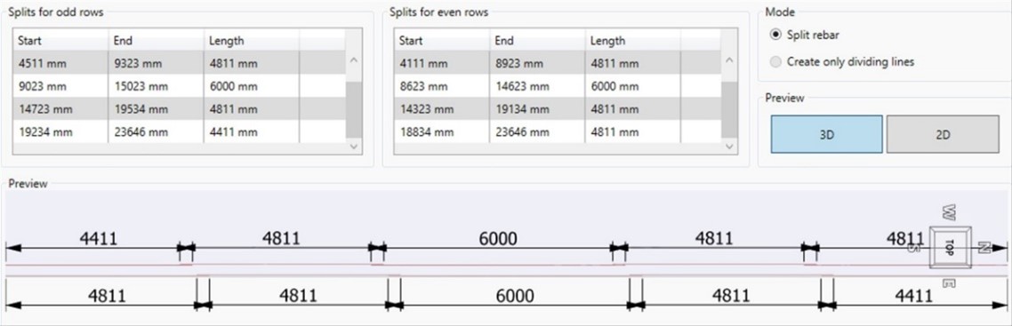
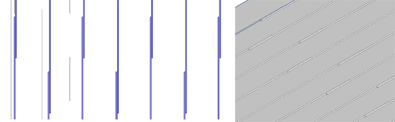
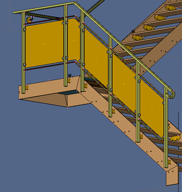
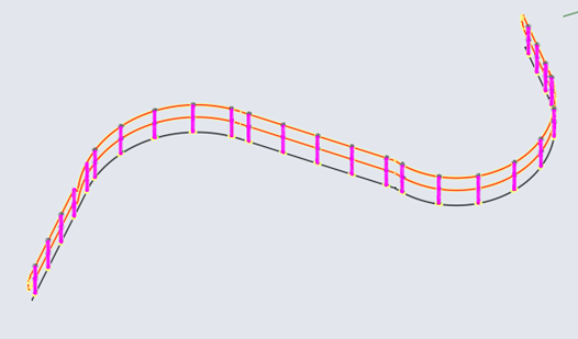
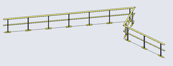
Final results:
Final Tips&Tricks
- Pay attention to rebar styles (Standard and Stirrup/Tie)
- I recommend making dedicated View Templates to each element category. This way you can automatically hide unwanted rebars or sections
- You can use multiple bending details tags
- You can use this tool also for the initial views the user needs to have in order to place the rebars. Generating drawings without multi-rebar annotations and bending details will be instantly done. You can use this in your advantage.