- Real-time energy simulation
ArchiWIZARD and his raytracing technology enables accurate and efficient simulation of solar and light radiation.
Simulate and evaluate the impact of architectural and technical choices interactively and quickly to optimize the bioclimatic performance, including solar and light studies, of a project from the first sketches.
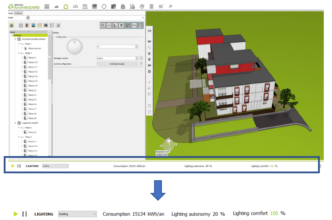
Results of light analysis in the bottom crossbar change in real time according to the modification of 3D model parameters by the user (for example building orientation, solar shading etc.).
- Solar and light tools
ArchiWIZARD has ergonomic and efficient tools to analyze in detail the sunshine, irradiation and natural light of projects and optimize the exploitation of solar and light resources. These features make it an essential solution for the visual and educational evaluation and demonstration of the choices made, whether for the installation of the building or the sizing of the bays, sun protection, photovoltaic installations, etc.
• Solar Imagery
• Projected shadows
• Solar receiver
• Lighting map
These tools can be easily used through ArchiWIZARD intuitive interface:
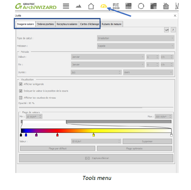
2.1. SOLAR IMAGERY
This feature allows to visualize solar radiation cumulation received on project surfaces. There 3 types of calculation:
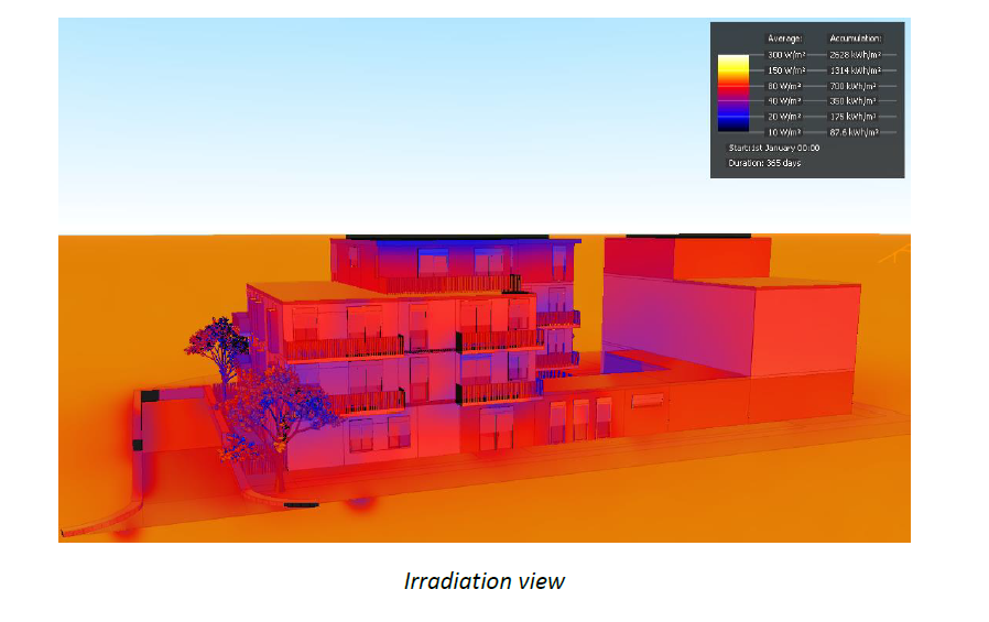
Irradiation
This represents the energy received by a point on a surface (walls, floors, roofs …) throughout the simulation period.
The flux received depends on the climate, the position of the wall (orientation, tilt) and masks present.
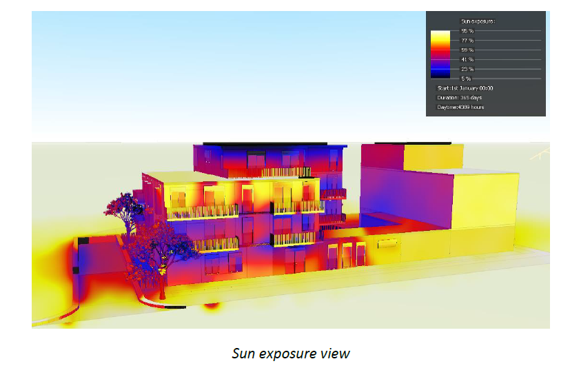
Sun exposure
This mode enables viewing of the time when a surface is exposed to direct sunlight compared to the time when the sun is up.
Sun exposure [%] = time when the wall receives direct sunlight [h]/ sunshine time [h]
The flux received depends on the climate, the position of the wall (orientation, tilt) and masks present.
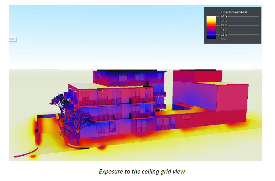
Exposure to the ceiling grid
This representation shows the percentage of ceiling grid “seen” per wall. The reference is a horizontal wall without a mask: its exposure to the ceiling grid is 100%. Accordingly, this parameter depends on the tilt of the walls and the mask presence. This map display reveals the impact of near and far masks on the project.
2.2. PROJECTED SHADOWS
This feature allows to visualize the drop shadows of the stage (building and its environment). There is two mode:
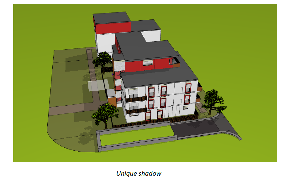
Unique shadow
Allows to visualize the shadow of the project and his environment on a specific time (month/day/hour/minute).
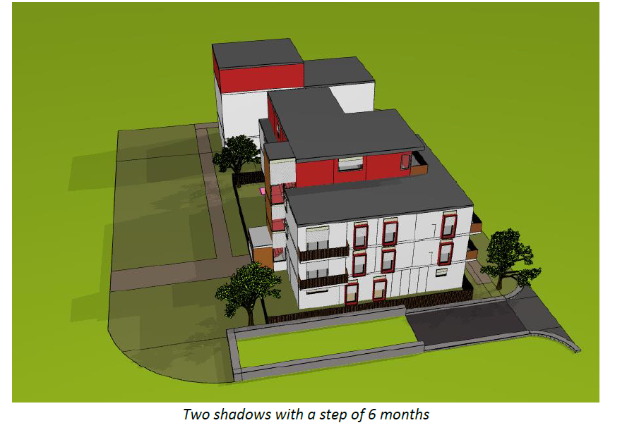
Multiple shadow
Multiple shadows mode works as unique shadows mode. The difference is that the user can chose a step of time and visualize the evolution of the shadow for each step at the same times on the 3D model
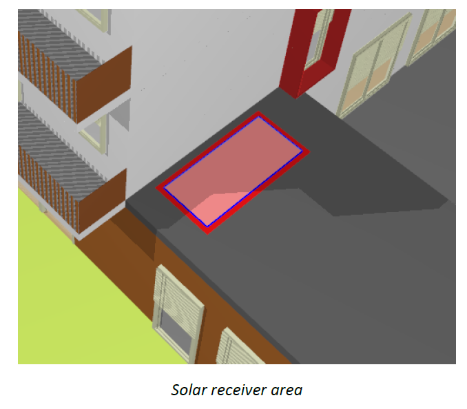
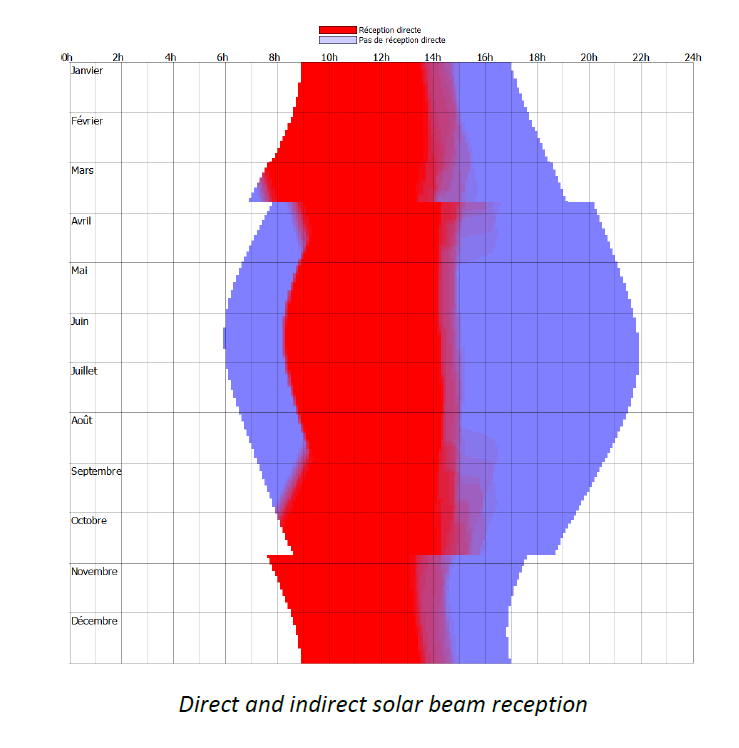
2.3. SOLAR RECEIVER
Solar receiver is used to quantify solar and natural light received by a defined area. This area can be placed manually by the user.
The solar reception makes the difference between direct, indirect, and diffuse solar beam.
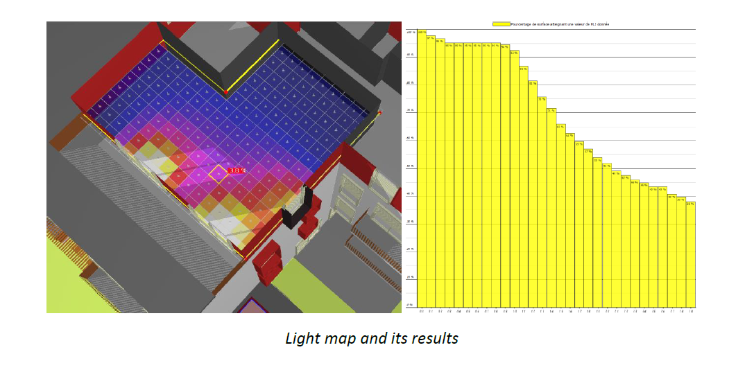
2.4. LIGHT MAP
The lighting map enables display of the daylight factor or lux illumination received on a horizontal plane in the scene.
It considers the geographical location, masks, the position of openings and their characteristics. Illumination with direct sunlight is also represented.
Artificial lighting is not considered.
This plan, represented by the map, can be positioned around the scene, interior as well as exterior of a project.
ArchiWIZARD has multiple tools to conduct studies on solar or light radiation from a project. These tools benefit from raytracing and allows accurate and adapted results.
