Advance Design allows creating a new type of steel slab/deck: non-composite steel slab. The non-composite slabs may be used as floors in lightweight structures or as a form for reinforced concrete slabs.
Steel decks are created directly in the graphic area. The procedure for creating a non-composite steel slab is similar to the ones for other slab type elements. The position of the slab is specified by entering the coordinates on the command line or by snapping to other objects. The plate type can be selected from the General > Type drop-down list in the Properties window.
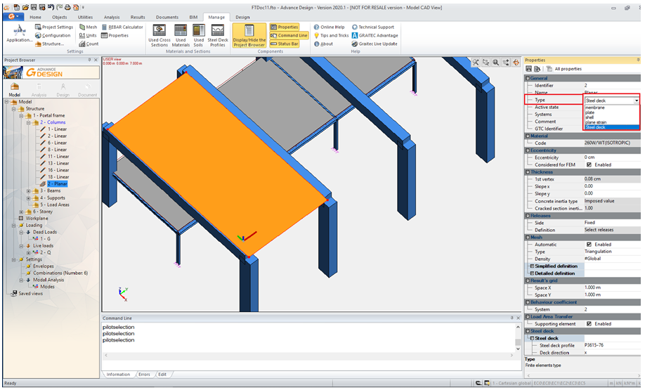
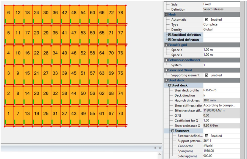
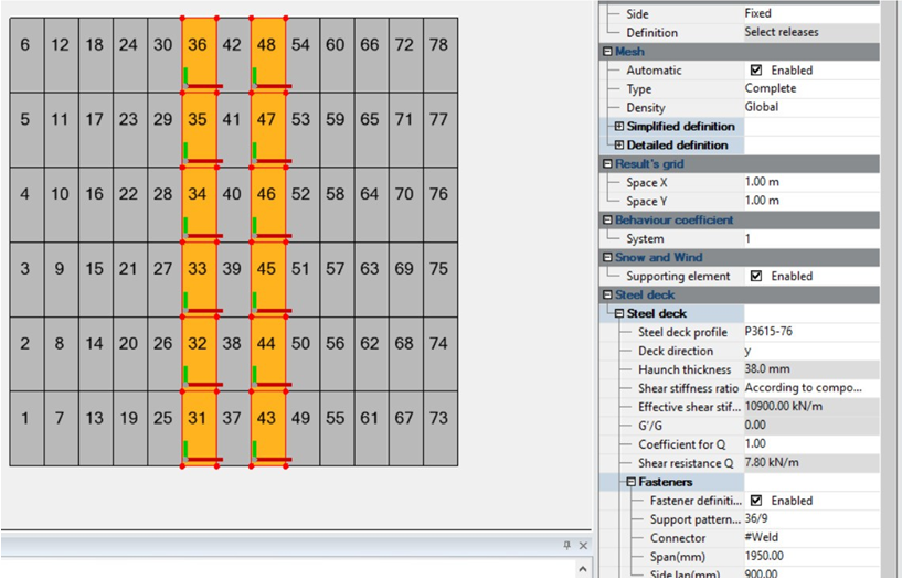
The element’s attributes can be configured in the Properties window.
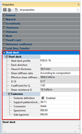
In the Properties window you can define the material type (according to the producer’s description), the type of profiled steel sheet, the steel deck connections, etc.
Working example
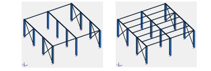
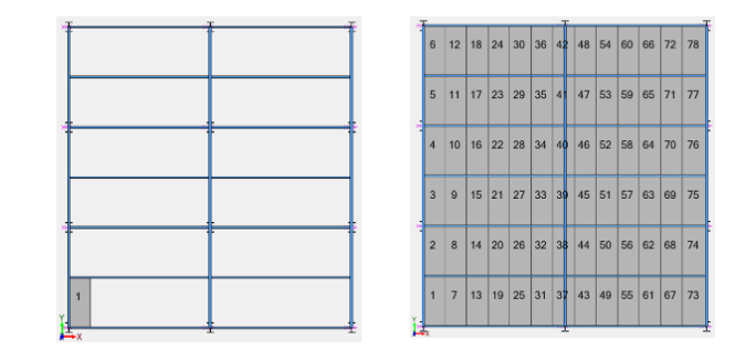
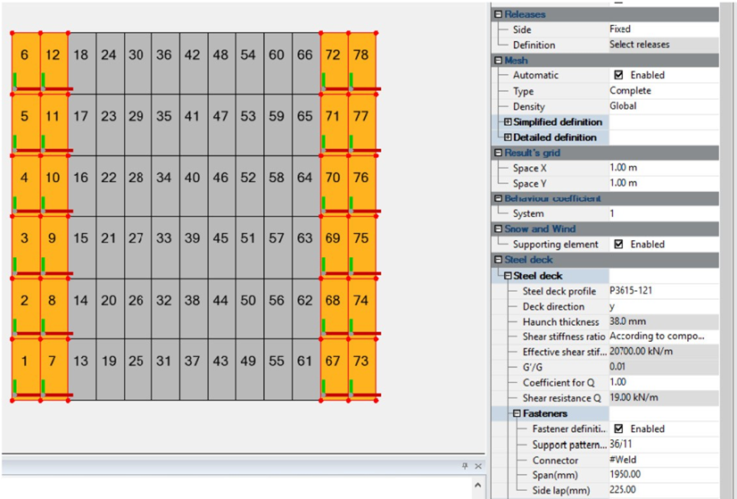
Let us assume we need to use a steel deck floor on the structure below (1-a). First, the position of the secondary beams (joists) is established as a function of the steel deck profile allowable span. For deck profile P3615-76, a span of 1950mm (1-b) is chosen.
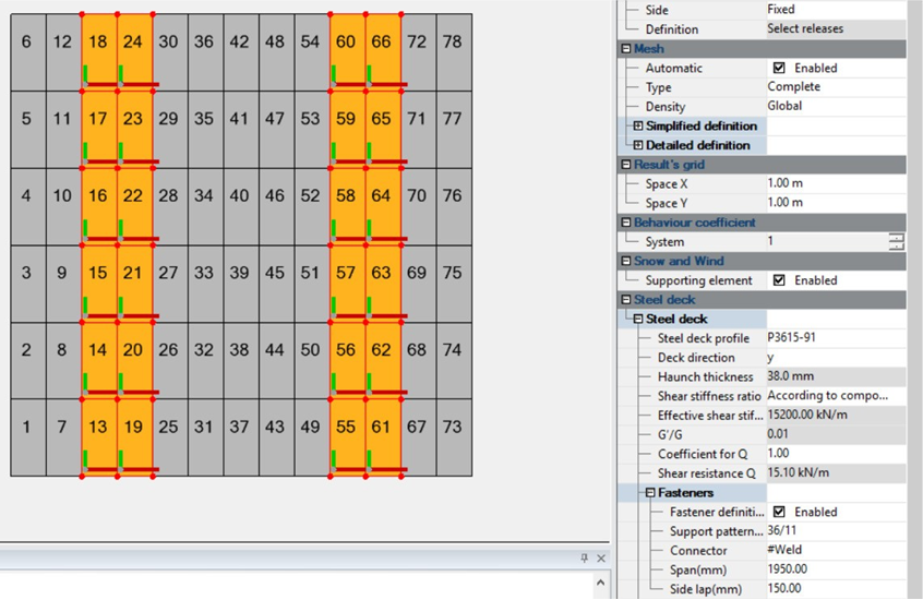
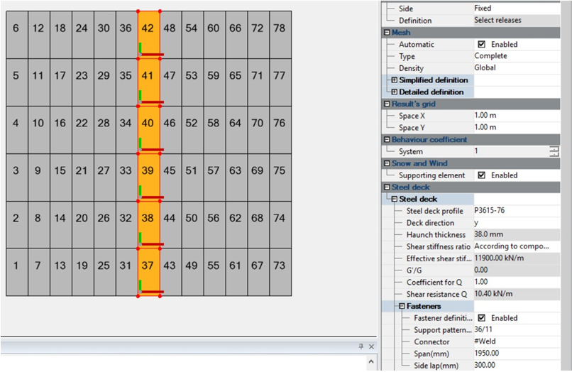
The width of the profiled steel sheet is 914 mm and will be placed along the Y global direction. In order to properly consider the interaction with the joists, the 914 mm-wide deck sheets will be drawn one by one between them (2-a, 2-b). It is recommended to draw the deck parts in numerical order for a straightforward use of results. The steel deck definition is the same for all elements (3-a).
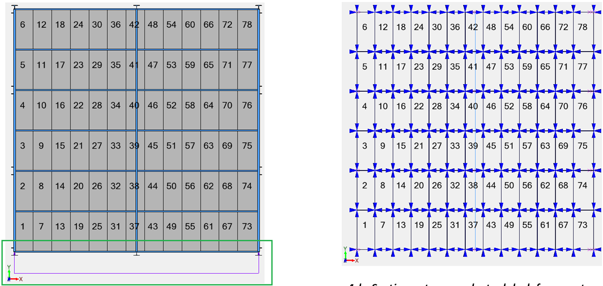
The lateral walls act like a diaphragm between the foundations and roof/floor. They take over wind pressures and distribute them at the horizontal level. The roof/floor diaphragm receives a linear load from the side wall.
We therefore run the analysis considering a linear load of 25kN/m (4-a). Advance Design automatically generates a set of four section cuts on each steel deck fragment.
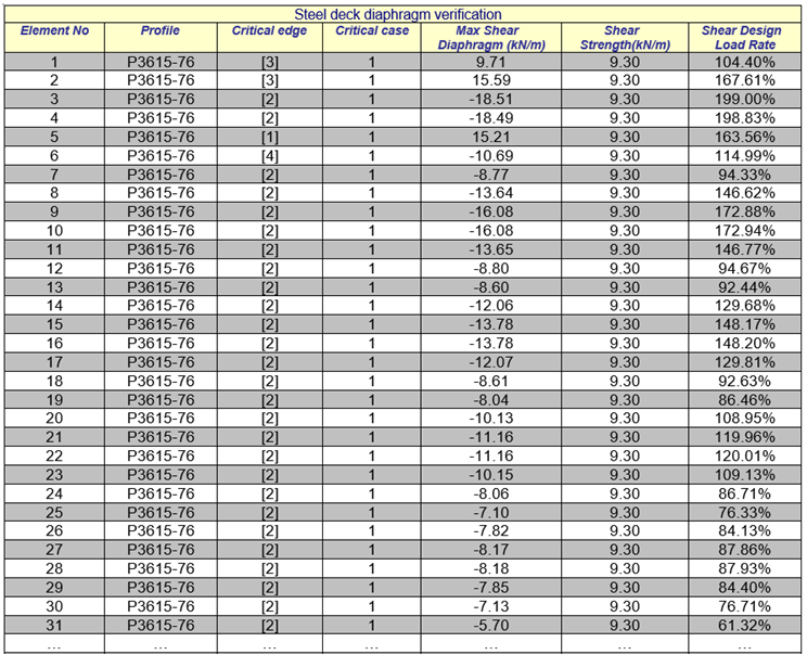
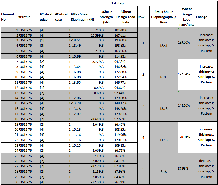
The Steel deck diaphragm verification report provides the maximum shear diaphragm for each element. The value results by dividing the Txy section cut tensor to the side length. The shear diaphragm is then compared to the steel deck Shear Strength (5-a, custom table 5-b).
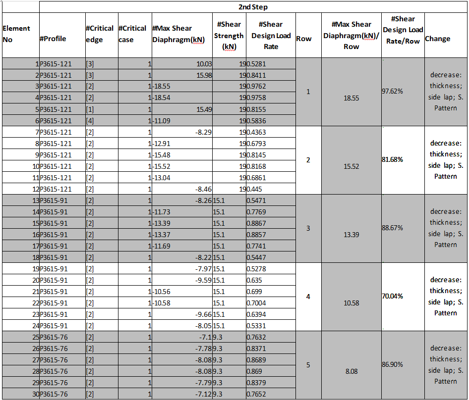
An efficient use of materials is met by using different steel decks and connections. Therefore, one adjusts the deck settings for all the elements on a row according to the Shear Design Load Rate deficit (6-a, -b, -c). If the capacity exceeds the shear diaphragm, the number of fasteners or the steel sheet thickness may be reduced (6-d).
In the second step, you can notice the material optimization achieved by the properties changes (custom table 7-a).