In this short article, we will look at one of the model validation methods available in Advance Design – displaying modelled elements in color according to selected criteria. Although this functionality is more general and can be used simply to improve the way a model is presented in a view or for documentation, today we will focus on its advantages for model verification.
Let us start with the topic of verification of local system of axes of surface elements. Checking and eventual change of local systems is an important step in the verification of the model, because by proper arrangement of local systems we have control over the uniformity of the FEM results and the reinforcement directions. Each modelled planar element has its own local system of axes, which is set automatically. Knowing the basic rules of automatic local axis system setting (as for example that the x-axis of the local system is usually defined along the first edge of the drawn contour) we can often control it ourselves. However, this is not always convenient or possible, especially when the model has been imported. Checking the local layout of axes for one or more elements is not a problem – we can simply select a surface element and we see its local axis symbol by default. The colors of the axes correspond to the colors of axes of the global coordinate system, i.e., the red axis is local x, the green one is local y and the blue one is local z.

However, it is much more interesting how we can quickly check the local axis settings for a larger number of elements / for the whole model. To do this in Advance Design, we can use a very versatile tool to display objects in color according to selected criteria, available in the Display Settings window. In the ‘Color’ command group, there is a list for selecting coloring criteria, as well as additional options including displaying a legend and displaying the element’s local system axis during element selection.

For our purposes, of the many criteria available here, three will be useful to us: Local x orientation, Local y orientation and Local x orientation. All these modes are used to indicate in which direction the axes of the local system are oriented relative to the global system.
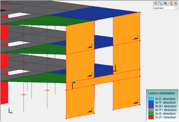
Take a look at the image below showing an example of the effect of using the ‘Local x orientation’ option.

The surface elements are colored and thanks to the legend we can immediately see how the local x-axis is oriented. For example, dark blue means that the local x-axis is pointing in the Y- direction of axis of the global system, light blue means that it is pointing in the Z- direction (down), while red means that it is pointing in the Z+ direction (up). We can easily confirm this just by selecting elements, as then we can see symbols of local systems.
If we now want to unify the orientation of the local axes, all we need to do is select the relevant elements, which is very easy thanks to the colors, and then choose one of the dedicated commands: Local Axis or Local Axis on direction.
On a similar basis, we can verify the orientation of the other axes of the local system of planar elements, but in the same way we can verify the local systems of linear elements. Of course, for this purpose, it is best if we filter out only the linear elements for presentation. But the same types of coloring styles as for surface elements can be used for this purpose.

The layout of local axes is not all that we can verify with coloring. The same tool can be used to verify the correctness of the modeling according to other criteria – for example thicknesses.

On the same principle, we will also check the cross-section of linear elements or the material that has been assigned to different elements of the model. But that’s not all. In a similar way, we can color elements according to their type, system assignment, or super element affiliation. And, other objects, such as loads by category or steel connections by type. I recommend that all Advance Design users become familiar with all the available coloring criteria because using them increases the control over the model.
