In order to simulate the membrane effect in a structure in Advance Design, “DOF (Degree of freedom) constraint” object can be used with the Tx and Ty translations restrained. DOF constraint object is also named as Master-Slave connection. The command can be found in “Objects” ribbon tab:

The following properties regarding restraints definition are defined for the “DOF constraint” (Master-Slave connection):

For example, the response of the DOF constraint is compared with the response of a membrane in a simple 3D structure subjected to lateral loads. In this model, the elements’ self-weight is not considered.
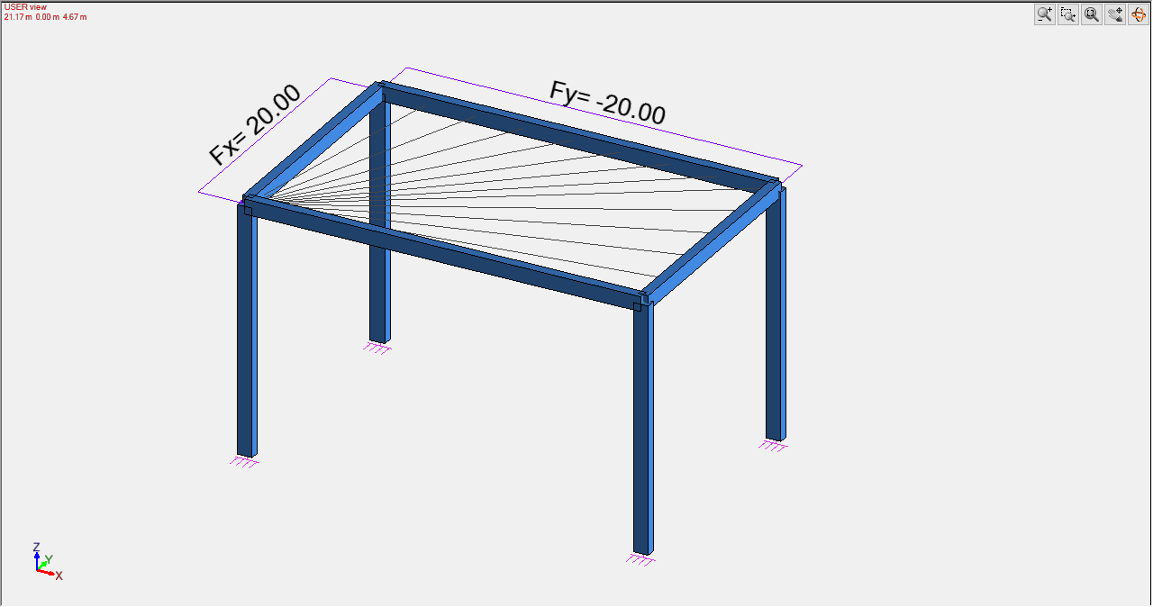

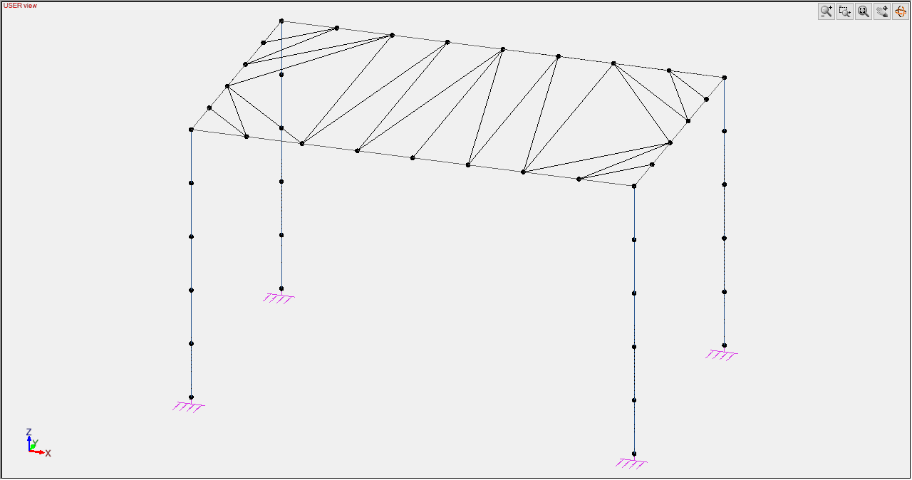
Since the master-slave connection imposes to all component nodes the same DOF restraints (translations/rotations), the master node can be placed anywhere on the perimeter. In order to simulate the same response, the nodes must be placed on the same position as the mesh nodes of the membrane:

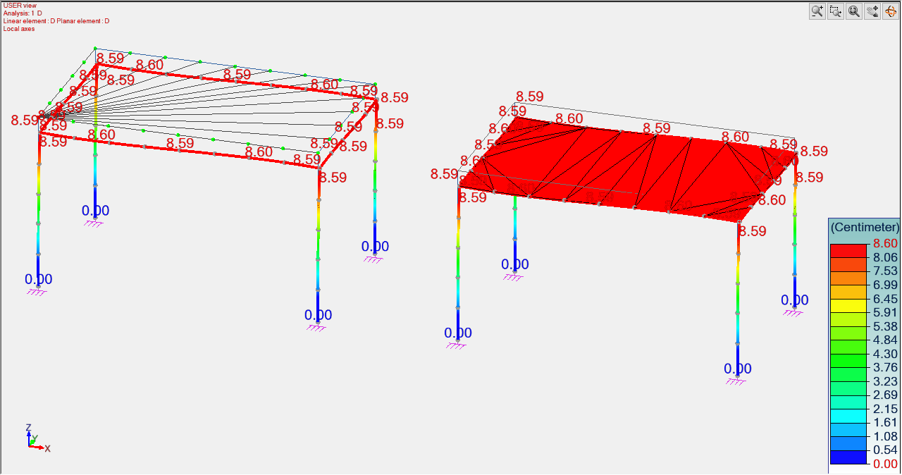
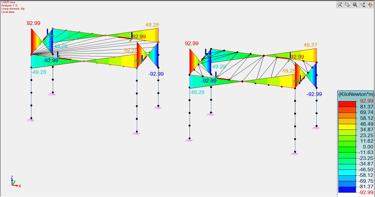
The similar response of the two objects (master slave connection with Tx and Ty translations restrained and membrane) can be verified by comparing the results of the FEM analysis: