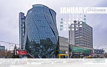
With calendar
Size: 1280×1024; 1600×900; 1680×1050; 1920×1200
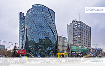
Without calendar
Size: 1280 x 1024; 1600 x 900; 1680 x 1050; 1920 x 1200
With calendar
Size: 1280×1024; 1600×900; 1680×1050; 1920×1200
Without calendar
Size: 1280 x 1024; 1600 x 900; 1680 x 1050; 1920 x 1200
With calendar
Size: 1280×1024; 1600×900; 1680×1050; 1920×1200
Without calendar
Size: 1280 x 1024; 1600 x 900; 1680 x 1050; 1920 x 1200
With calendar
Size: 1280×1024; 1600×900; 1680×1050; 1920×1200
Without calendar
Size: 1280 x 1024; 1600 x 900; 1680 x 1050; 1920 x 1200
With calendar
Size: 1280×1024; 1600×900; 1680×1050; 1920×1200
Without calendar
Size: 1280 x 1024; 1600 x 900; 1680 x 1050; 1920 x 1200
With calendar
Size: 1280×1024; 1600×900; 1680×1050; 1920×1200
Without calendar
Size: 1280 x 1024; 1600 x 900; 1680 x 1050; 1920 x 1200
With calendar
Size: 1280×1024; 1600×900; 1680×1050; 1920×1200
Without calendar
Size: 1280 x 1024; 1600 x 900; 1680 x 1050; 1920 x 1200
With calendar
Size: 1280×1024; 1600×900; 1680×1050; 1920×1200
Without calendar
Size: 1280 x 1024; 1600 x 900; 1680 x 1050; 1920 x 1200

With calendar
Size: 1280×1024; 1600×900; 1680×1050; 1920×1200
Without calendar
Size: 1280 x 1024; 1600 x 900; 1680 x 1050; 1920 x 1200
With calendar
Size: 1280×1024; 1600×900; 1680×1050; 1920×1200
Without calendar
Size: 1280 x 1024; 1600 x 900; 1680 x 1050; 1920 x 1200
With calendar
Size: 1280×1024; 1600×900; 1680×1050; 1920×1200
Without calendar
Size: 1280 x 1024; 1600 x 900; 1680 x 1050; 1920 x 1200
 The article describes how we can create reinforcement and formwork drawings for structures with a complex geometry, namely bridge abutment using Advance Concrete. The bridge abutment is a part of infrastructure which is created at the ends of the bridge in order to take the transmitted loads of the bridge superstructure and the supports of the access path to the bridge.
To define the chosen geometry, an ACIS block can be created or the complex geometry can be divided into several blocks having a simple geometry which can be assembled in order to obtain the initial model.
We chose the second method for reasons related to the flexibility of Advance Concrete while modeling volume elements.
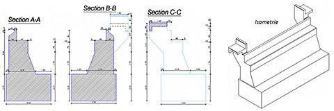
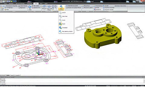
How to create any 3D concrete shape
Advance Concrete provides the creation of any 3D and 2D shapes. The predefined concrete shapes can be chosen from the library or new ones can be created. To add a new concrete shape it is enough to create a closed contour and then save the shape in the concrete library. These new shapes can then be used either in the current drawing or for other projects.
The created concrete elements are defined as beam and column structural elements. These are positioned one in regard to the other, composing the entire concrete ensemble.
How to obtain a 3D reinforcement cage for special concrete shapes
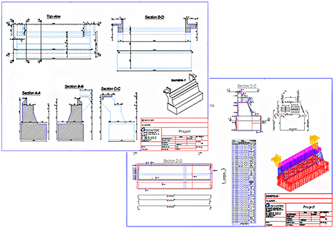
The reinforcement drawing is created by selecting all the concrete elements. In the created reinforcement drawing, sections are added through the specific concrete zones.

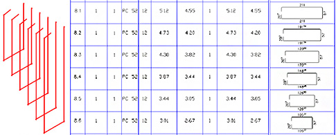
The definition bars are created in one section and then distributed in elevation or top view. Several types of bars (straight, U and L bars) and distributions (linear, variable, multiple and quantitative) are available for use. The most frequent reinforcement bars are polygonal and straight bars and linear and variable distributions. Concrete covers can be set for each leg of the polygonal bar.

 A reinforcement bar distributed in one view will automatically be available in all views, as long as the 3D power option is activated in the reinforcement drawing.
 In order to obtain a correct reinforcement cage, the collisions between bars have to be avoided. The bar collisions can be visualized in 2D and 3D representations. They can be easily checked and corrected, at any point.
The bar detailing and reinforcement symbols can be done both manually (they can be customized and saved in the reinforcement symbol library) and automatically.
The bars numbering and lists creation is automatically done. Sub-entity marks are assigned for variable distributions, emphasizing that the variable distribution belongs to a single shape definition bar.
The drawings are created according to standard STAS 438/1,3 -89. The drawing creation according to other standards is similar.
Formwork details
The formwork drawing is created by adding the desired sections and elevations for structural elements, assigning specific hatches and line weights. The dimensioning of sections is quickly done by adding intersection and level dimensions.
Layout and Print
The reinforcement and formwork drawings can be placed in any page format. Also the views can be grouped and the title block can be attached according to the chosen format.
Numbering of the reinforcement bars and lists can be done in layout mode. The drawings can be printed one by one or by selecting several from the available print window.
Test it yourself
We have shown a simple example of a formwork and reinforcement cage created for a complex shape of the structural element. If you want to see the model described above, please download the specific model and drawings from here or, as a pdf file from here.
The example was created in Advance Concrete 2013.

With calendar
Size: 1280×1024; 1600×900; 1680×1050; 1920×1200
Without calendar
Size: 1280 x 1024; 1600 x 900; 1680 x 1050; 1920 x 1200
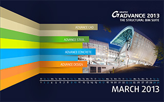
Launched at the end of February 2013, BIM GRAITEC ADVANCE is the global CAD / Analysis & Design solutions for the construction engineering field. Advance CAD is part of the GRAITEC structural BIM solution and a newcomer in the GRAITEC Advance suite.
GRAITEC’s Advance CAD is fully compatible DWG® CAD software. It provides its users a simple, natural and economical solution to the frequent requirements of drawing creation and modification. Advance CAD creates all 2D entities (lines, poly-lines, arcs, circles, polygons, etc.) and associates all desired colors, line styles and shading. Concepts such as “layers”, “snap points”, “windows” are available as well as all navigation features (zoom, pan, orbit, etc.). Advance CAD can also create and handle 3D solids (cubes, spheres, cylinders, etc.) and perform Boolean operations.
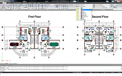
In the complete 2D/3D CAD environment of the software, you can find all the common CAD tools and features, several innovative features meant to enhance user productivity, but also 3D modeling tools for drawing 3D solids, functions that allow face editing for 3D elements, all these wrapped up in a user-friendly, simple and intuitive interface.
The user interface is designed to get you familiarized fast with all the software elements and functionalities: quick access toolbar manager, ribbon tabs, customizable menus, keyboard shortcuts, auto-completion of commands, selection filters. It also offers you the possibility to customize general settings such as display, paths/files, user preferences, crosshairs or profiles.
Advance CAD provides full compatibility with AutoCAD®, using most of the same file formats including those for drawings (.DWG files), commands, line types, hatch patterns, and text styles. Advance CAD reads and writes .DWG files in their native format without data loss, from AutoCAD® 2012 and going all the way back to Version 2.5, including AutoCAD LT®. Because Advance CAD uses Autodesk® DWG™ format as its native file format, no conversion is required.
Advance CAD offers users all the professional 2D and 3D modeling tools and functionalities and at the same time it is cost effective.
With calendar
Size: 1280×1024; 1600×900; 1680×1050; 1920×1200
Without calendar
Size: 1280 x 1024; 1600 x 900; 1680 x 1050; 1920 x 1200

With calendar
Size: 1280×1024; 1600×900; 1680×1050; 1920×1200

Without calendar
Size: 1280 x 1024; 1600 x 900; 1680 x 1050; 1920 x 1200
With calendar
Size: 1280×1024; 1600×900; 1680×1050; 1920×1200
Without calendar
Size: 1280 x 1024; 1600 x 900; 1680 x 1050; 1920 x 1200

With Calendar
Size: 1280×1024; 1600×900; 1680×1050; 1920×1200
Without calendar
Size: 1280 x 1024; 1600 x 900; 1680 x 1050; 1920 x 1200

With Calendar
Size: 1280×1024; 1600×900; 1680×1050; 1920×1200

Without calendar
Size: 1280 x 1024; 1600 x 900; 1680 x 1050; 1920 x 1200
 We are pleased to announce the release of Service Pack 2 of Advance Steel 2012!
Service Pack 2 has a set of enhancements and provides the following advantages to users:
Any customer under maintenance contract can download Service Pack 2 from the GRAITEC Advantage web site: www.graitec.com/advantage

With Calendar
Size: 1280×1024; 1600×900; 1680×1050; 1920×1200

Without calendar
Size: 1280 x 1024; 1600 x 900; 1680 x 1050; 1920 x 1200
