Revit propose a process to create reinforcement for most structural members, based mainly on two steps: first place the rebar shape in an appropriate section view and then distribute it in an elevation or the opposite, place the rebar shape in an elevation and then distribute it in a section (for longitudinal bars for example).
This manual and repetitive process therefore involve multiple manipulations and frequent switching between Revit views.
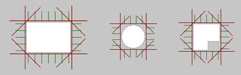
Whether for slabs or walls, the reinforcement of any kinds of openings is a recurring operation during projects. This technical aspect is addressed by one of the functions of the Graitec PowerPack, Reinforcement Openings.
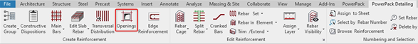
This Openings command is used to quickly generate constructive reinforcement around openings. It is available on the PowerPack Detailing ribbon.
The command enables the generation of reinforcement around openings on slabs and walls. It allows as well rebars generation for multiple separate openings at once. For a selected opening , it opens the configuration window with parameters related to concrete cover and tabs for different reinforcement bar types.
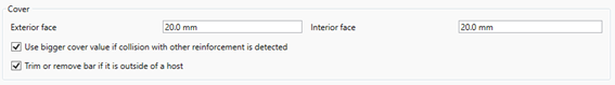
The Cover section allows the manual control of the cover, the automatic cutting of bars in case of holes close to the edge and the option to automatically adjust the cover to the existing reinforcement, to keep the correct 3D arrangement of bars.
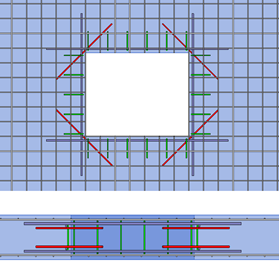
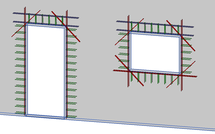
The remaining parameters are available on independent tabs separately for four optional reinforcement types: Main bars (longitudinal bars along edges), Diagonal bars (bars that are perpendicular to bisectors of corners), Edge bars (transverse bars along edges) and Lintel bars (longitudinal and transversal bars above openings on walls). Thanks to the wide range of settings, many different bar configurations are possible.
This new version 2022 has added a special option of opening rebar for door by the possibility to add or not the bottom diagonal rebar.
In the case of non-rectangular shapes of openings, the reinforcement is generated on its rectangular external perimeter
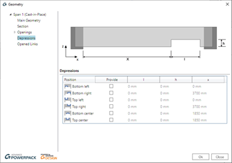
For beams, users may have to deal with several situations with openings such as placed within the beam, a depression … For all those situation, Graitec PowerPack provide some dedicated tools.
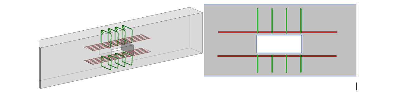
Firstly, the command Main bars or Constructive Dispositions can generate a 3D rebar cage on beam, even those one with custom shape including openings and depressions.
Then, it is also possible to add reinforcement around an opening in a beam with a dedicated command. This opening could be created by the native command By face.
All connections available in the Steel Connection module can be designed using all combinations or envelopes created from those combinations.
The possibility to choose how to use the combinations in the design process is available in the Design Assumptions dialog.
By selectingEnvelopes method, the calculation will be performed using only the combinations that provide Max/Min of the design forces using certain filtering criteria done in Advance Design Steel connection.
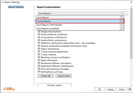
The envelopes that are considered now in calculation can be seen inside the new Combinations report or inside detailed or intermediate reports in the Load combinations chapter.
The Combinations report added to the available report list for each joint type will display only theLoad combinations description chapter, which will provide an easier and faster way to access the envelope list.
As have been mentioned, there are two options possible: All and Envelopes.
Now let’s see how the selection affects the behavior during calculation process.
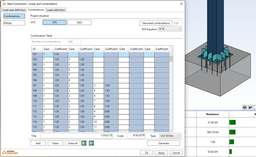
Combinations = All
For Combinations set on “All”, the Advance Design Steel Connection is using all the combinations generated to design the connection.
Example:
For the Base Plate connection for a tubular column as on the picture below, the number of combinations is 181, and all are used for design calculations. It influences the report (as a table listing all the combinations is long), but the most important is that due to the number of combinations, the calculation time is relatively long.
Combinations = Envelopes
For Combinations set as “Envelopes” the module will calculate the connection using just some of the combinations which are fulfilling certain criteria.
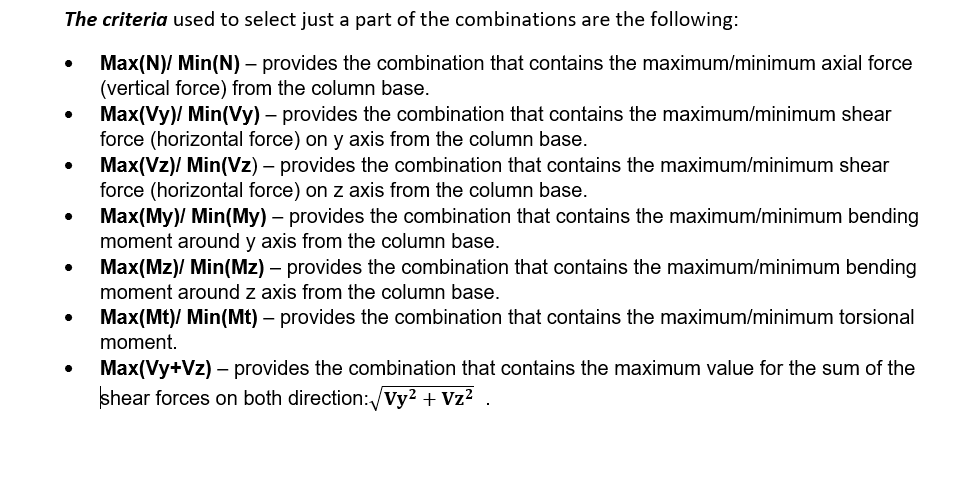
The criteria used to select just a part of the combinations are the following:
Based on these criteria, Advance Design Steel Connection module is selecting the combinations that compliant with one or more criteria and does the design calculations based on the selected combinations.
The calculation time decreases, and the report is much more compact as only the selected combinations will be listed.
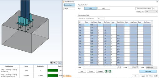
Example:
For the Base Plate connection for a tubular column as on the picture below (having more load cases that the previous example), the number of combinations is 482. But this time calculations are done with “Envelopes” of combinations.
Even there are 482 combinations, thanks to the envelopes, the calculation time is less than for the previous example. And in addition, the report does not have pages full of combination tables and it is generated much faster. The Load combinations description table on the report contains now only several combinations that are fulfilling one or more criteria. And the connection is verified using these combinations
As the 2022 version of GRAITEC Advance Design introduced the Crane Moving Loads feature, in this short article we will take a look at the moving loads available in Advance Design – the Traffic load and the new Crane load. As the traffic load generator has been available for a long time, I will present only brief information about it and focus mainly on crane loads.
Moving load panel on the ribbon
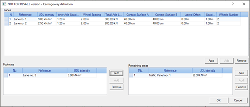
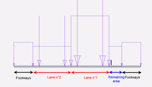
Let us start with the traffic load. The traffic load generator enables us to create traffic loads on road bridges according to EN1991-2 (Section 4). In order to create the appropriate traffic loads on the road bridge (on planar elements), we define graphically the elements composing the carriageway: one or several traffic lanes, remaining areas and footways or cycle-tracks.
Carriageway definition
The next step is to add a Traffic loads family and select the appropriate load model, according to the provisions of the Eurocode. Five load groups are available, containing respectively:
gr1a – combination of the concentrated loads (Tandem Systems) and the Uniformly Distributed Load (UDL System) with the uniformly distributed load on footways.
gr1b – a couple of concentrated loads that represent a single axle of a truck, for creating concentrated forces along the lane.
gr2 – combination of the concentrated loads (Tandem Systems) and the Uniformly Distributed Load (UDL System) with braking and acceleration forces and centrifugal forces.
gr3 – uniformly distributed load on footways.
gr4 – uniformly distributed load on footways and traffic panels.
Traffic load model selection
After automatically assigning the load parameters to the roadway, we are ready for load generation in the model.
Carriageway load parameters
Depending on the load model selected, this results in load cases that include uniform loads as well as a series of consecutive steps in the position of the concentrated forces from the vehicle wheels.
Uniform loads and moving loads from vehicle (all steps are shown)
Loads in section for one of the selected steps
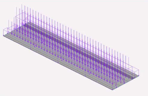
For loads from cranes, the process is somewhat similar. The first stage consists in defining graphically the route of the crane forces – it can be a single polyline to model the forces moving along a single rail (for monorail crane modelling) or two parallel lines to model the route for the forces from two trucks on both sides of the bridge crane.
Runway for the bridge crane placed on two beams
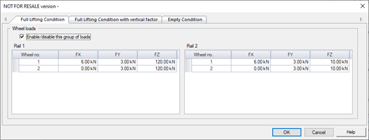
The next step is to add a Crane object. It is used to describe the geometry, such as the number and spacing of the wheels, and to describe the forces from the wheels.
Basic crane geometrical data
In the simplest case, the forces on each wheel can be defined manually, separately for each wheel. But it is also possible to use three different automatic methods, so that the wheel forces are automatically determined according to the rules of the standard.
Choice of force generation method
We have three methods available for the automatic determination of forces:
By crane loads(EN 1991-3) – for defining wheel loads automatically on the basis of entered crane loads, by using Eurocode EN 1991-3 rules. In this method several loads of different origin (e.g. loads from crane self-weight, from the weight of the load, from braking forces, etc.) are separately entered for each wheel. These load components are combined with the dynamic factors and the final wheel forces are determined. As the result this method gives several groups of load sets (ULS Group 1 to 6), according to the EN 1991-3.
By crane parameters (EN 1991-3) – for defining wheel load automatically on the basis of entered crane parameters, by using the Eurocode EN 1991-3 rules. The main difference compared to the previous method is that the values for each wheel are not entered, but the crane parameters (like self-weight of the bridge, self-weight of the trolley and the crane capacity) are given. The output is the same as for the previous method – six groups with sets of forces for each wheel.
By crane parameters (ASCE/NBCC) – similar to the previous one, so we do not enter the forces on individual wheels, but such loads are calculated automatically on the basis of entered crane parameters. But this time the method of automatic load generation is based on the general method, related to US/CAN standards (especially ASCE). But it is worth to mention, that the load generation rules are generic and are essentially independent of any standard.
Groups of loads per wheel calculated acc. By crane parameters (ASCE/NBCC) method
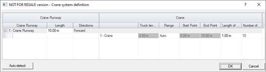
With the crane runway and the crane with the forces on the wheel, we can proceed to the next step, which is the definition of the load family. Here we determine the range of crane movement and the number/length of moving load steps.
Definition of move parameters for crane load family
The generation of crane moving cases is done automatically after using a ‘Generate’ command available when right click on the Crane Load case family. After it is run a set of moving load cases are generated, separately for each crane and each step position. They contain the forces from all wheels in a given position. Depending on the definition of the crane, these are both vertical forces and horizontal transverse or longitudinal (from braking) forces.
Load cases for each wheel position with forces
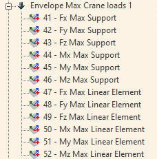
Together with the load case generation, sets of force envelopes from all force positions are also generated.
Automatically created envelopes
Importantly, we can define more than one crane and place them on the same or different runways. In this case, the program will generate for each crane a series of all force positions and then, when the envelope is generated, only the possible combinations of crane positions are considered.
One of the combinations of positions of 2 bridge cranes on the same runway
The final load combinations are defied by using typical load cases (dead, live, wind…) and Crane Envelopes. This is particularly important when there are a large number of crane steps and especially many cranes, as the final combinations consider only a dozen or so envelopes instead of thousands of crane position combinations.
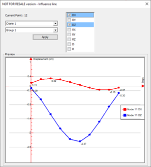
The static calculation and the results for the combination cases do not differ from other load types and you can check the results for each crane position as well as for the envelope of the crane forces. Specific to crane is a new type of graphical output – the influence line diagram. It shows graphically the value of the result at a given point for all successive positions of the crane. Although in this version of the program the influence line diagram can only be displayed for displacements in structure nodes, it is one of the additional tools useful when analyzing the results.
June 1st we released our products for their 2022 versions, this covers the entire Graitec portfolio, well within that there are few things that stand out to me coming from the Steel detailing and design background, that sound a clear intention of Graitec in this area.
The first one is within our analysis engine ‘Advance Design’, the New feature of Cold Formed Design to EC3. This is a Game changer for those engineers using portal frame constructions and trying to design the most efficient systems for those structures.
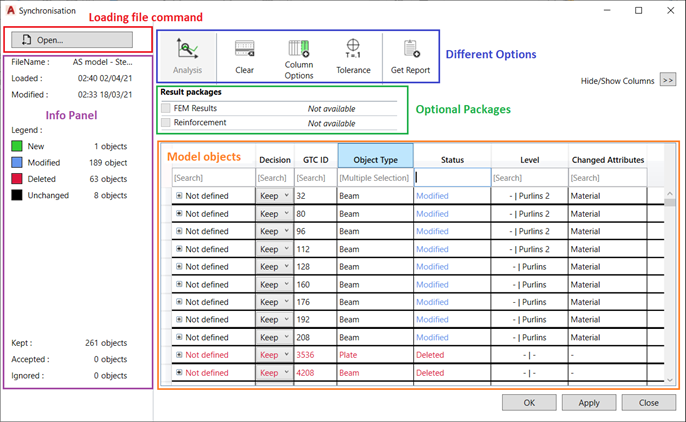
The next one is more in the link between our Advance Design platform and Autodesk Advance Steel for the transfer of model data, for this version we have a Newly design GUI and Mechanism for the Synchronization of Data using the Graitec GTCX file format. This new interface allows form many options to optimise what you wish to transfer and sync,
Figure 1-Example of new Dialog
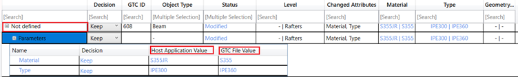
Within the file and the options available we have the ability to have a dedicated object ID, object type, Status display for New/Modified/Deleted, Material, Geometry, Element Type.
Figure 2-example of column types
Having all these options, we now have also filter options available, to help you dig down and only see the data you require.
Figure 3- filter example.
Also, the file has now the option to contain the level of the element within the model space. It has two options to show the host location and the allocated level in the GTCX itself.
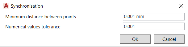
Also, all important one for model Tolerance, this allows for the user to control during the Sync process the variation between the model elements is acceptable, based upon those numeric values.
Figure 4- tolerance example
Concrete elements are now also considered for the GTCX file and the transfer, presently standard column, and beam shapes for this version, but sure other more complex shape definitions will be added to this new feature.
There are a lot more elements and options to the GTCX and the New Sync process, these are explained in depth in the what’s new, that is available to customers via the Graitec Advantage site.
Powerpack Premium Steel – Stairs and Railings
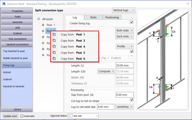
Within the premium model, particularly for Stairs and Railings we have a great new feature for those working with panelised balustrades/railings, that is the inclusion of ‘Lugs’ to the panels.
We can now add vertical and horizonal/incline lugs.
This may only look like a small feature but for those of us that have to detail these, this will be a real time saver.
Figure 5-Lugs dialog – perpendicular/incline to rail
Figure 6- Lugs – vertical to post.
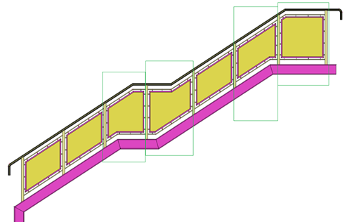
Anther part of the railings in the actual placement of panels within the rail, previously there where some limits on what we could achieve, but again the development team have worked on this to improve this function to accommodate more complex arrangements.
Figure 7- complex panel shaping
This also works with the frames type panels as well.
Figure 8- framed types
A new option is to allow for the user to turn off the top rail and still have the panels, this can be useful in the situation of external fencing panels and picket type fencing arrangements.
Figure 9- fencing arrangement/ Stairs/ pickets etc.