With Graitec PowerPack for Revit, a specific functionality has been introduced for assigning reinforcement to a layer (for example Top or Bottom) for easy and quick filtering of the reinforcement.
The layer might refer to a geometrical location of reinforcement but also to another purpose, such as its function.
The information about the assigned layer is stored using shared parameters: G.Rebar Location for Structural Reinforcement and G.Fabric Location for Structural Fabric Reinforcement.
The assignment is done automatically and manually. The automatic method is applied during reinforcement generation using calculation modules or reinforcement generators in PowerPack. For example, the top bars in the foundation have an automatically assigned value T (a default name for a top reinforcement). Automatic assignment is made to the selected rebars, for example in the case of a foundation to the lower and upper bars in the pad.
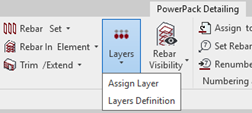
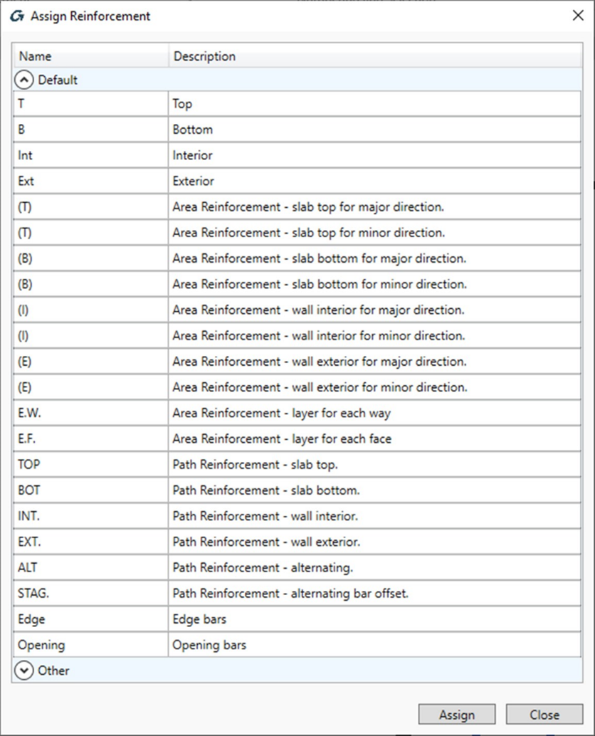
The manual assignment is done for selected reinforcement using the Assign Layers command, which is available in the PowerPack Detailing ribbon.
The Assign Layers command opens a special dialog with the list of default/predefined layers.
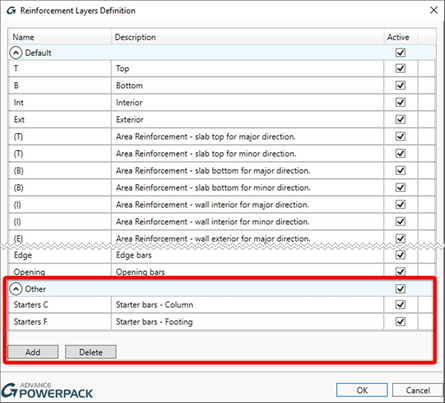
The content of the list is based on the configuration from the Reinforcement Layers Definition window, opened by the Layers Definition command. The user can modify names for default layers, use the Active option to limit the list of layers that can be available during the assignment and add new positions/layers to the Other group.
The value of the layer parameter is mainly used in the new options of the tools for controlling the reinforcement visibility
In fact, in the Rebar Visibility functionality, there is a group of options for selecting by layers.
When the Top or Bottom option is selected, then an additional filtering for reinforcement is activated, respectively by the top and interior or the bottom and exterior layers. When the Selected option is active then the selection of layers for displaying is done through the dialog opened by the Select Layers button .
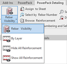
In addition, three new commands are available under the drop-down list under the Rebar Visibility: By layer, Hide All Reinforcement and Show All reinforcement.
Hide All Reinforcement and Show All Reinforcement allow you to quickly turn off or on the visibility of the entire reinforcement in a given view. By Layer allow you to quickly select the reinforcement to be displayed by using the Layer property.
This is particularly useful when generating drawings with separate views, e.g. for bottom/ top reinforcement for slabs or foundations.
Among the many features that make modeling in Advance Design easier, today we will look at two simple ways to create your own library of common elements. These options can greatly speed up the modeling of upcoming projects, especially if you often use the same elements.
The first solution is to save element properties to file for assigning them to other elements in a current or new project.
Let us see a simple example. Consider a steel structure that has already been designed and verified. Thus all the individual elements such as columns, purlins, lateral bracing etc. are not only correctly modeled but also have their design parameters set correctly.
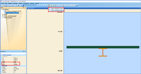
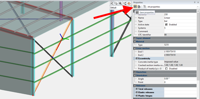
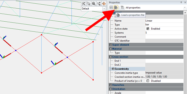
If in the next project some of the elements should be modeled and parameterized in a similar or identical way, we can create our own library easily. To do so, simply select an element (e.g. bracing) and use the ‘Save properties’ command located at the top of the properties window (Figure 1).
Figure 1
Importantly, all properties, both basic, such as section or material, as well as others, including release settings, system assignments, and dimensioning parameters, are included in such a saved template.
The template will be saved as a file in XML format, and you can decide on its name and location on the disk. In this way, you can create your own database of typical elements, both linear (steel, concrete or wood) and surface elements. Working with the next project, after modeling the geometry, we can select one or more elements of the same type (although not necessarily with the same properties) and load the properties using the ‘Load a properties file’ command (Figure 2).
Figure 2
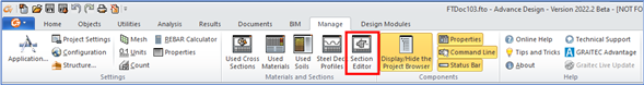
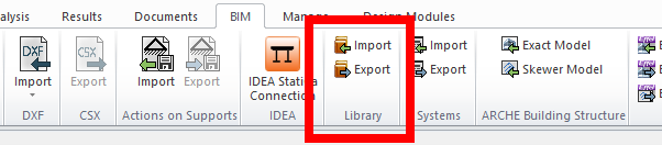
Let us now look at another solution. When we want to create a library containing many elements with information about their geometry, we can use a slightly different mechanism – saving selected elements to the library. To do this, we use the commands available on the BIM ribbon (Figure 3).
Figure 3
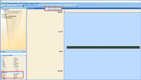
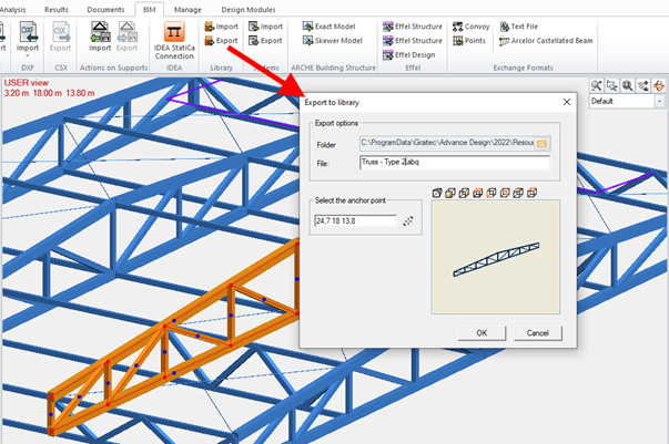
The procedure is also simple. Select the objects (it can be any selection of objects of different types, including linear elements, surface elements, supports, loads and others) and export to a file, specifying the insertion point (Figure 4). When inserting into a new project, simply select the file and specify the insertion point.
Figure 4
In this way, we can create a library of typical structural parts (for example, girders, frames, trusses, bracing systems) and, together with the geometry, all the properties of the elements are preserved, including the design parameters. But this mechanism is more universal and allows you to write any object, for example a layout of selected loads, into the library. This functionality is also useful when one or more users separately model different parts of a structure. Then the element libraries export / import tool makes it possible to assembly these parts into one single project.